
Micro current sensor precision calibration method and device, computer equipment and storage medium

A current sensor and calibration method technology, which is applied in the direction of measuring devices, instruments, and measuring electrical variables, etc., can solve the problems of small design distance, current measurement value error, and affecting sensor measurement accuracy, so as to improve accuracy and reduce measurement error. Effect

Active Publication Date: 2020-11-20
CHINA SOUTHERN POWER GRID DIGITAL GRID RES INST CO LTD +3
View PDF11 Cites 6 Cited by
  • Summary
  • Abstract
  • Description
  • Claims
  • Application Information

AI Technical Summary

Problems solved by technology

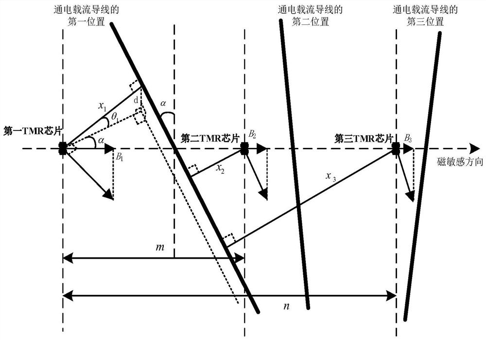
[0004] Compared with other magnetoresistance chips, tunnel magnetoresistance (TMR) chips (hereinafter referred to as "TMR chips") have unique advantages such as large magnetoresistance effect and high magnetic field sensitivity, and are widely used in miniature smart current sensors; Among them, the inventor found that there are at least the following problems in the traditional technology: the traditional TMR chip can measure the magnetic induction intensity in the single-axis or three-axis direction, and the sensor using three single-axis TMR chips to measure the current has been developed, and it has begun in the power grid application, but due to manufacturing and measurement errors, there is often a certain error between the actual distance between TMR chips and the design distance, and the design distance between TMR chips is generally small (millimeter level), making the relative error large, There is also a large error in the current measurement value, which affects the measurement accuracy of the sensor

Method used


Image

  • Micro current sensor precision calibration method and device, computer equipment and storage medium
  • Micro current sensor precision calibration method and device, computer equipment and storage medium
  • Micro current sensor precision calibration method and device, computer equipment and storage medium

Examples


Embodiment Construction

[0058] In order to facilitate the understanding of the present application, the present application will be described more fully below with reference to the relevant drawings. Embodiments of the application are given in the drawings. However, the present application can be embodied in many different forms and is not limited to the embodiments described herein. On the contrary, the purpose of providing these embodiments is to make the disclosure of this application more thorough and comprehensive.

[0059] Unless otherwise defined, all technical and scientific terms used herein have the same meaning as commonly understood by one of ordinary skill in the technical field to which this application belongs. The terms used herein in the specification of the application are only for the purpose of describing specific embodiments, and are not intended to limit the application.

[0060] It can be understood that the terms "first", "second" and the like used in this application may be...


PUM


Abstract

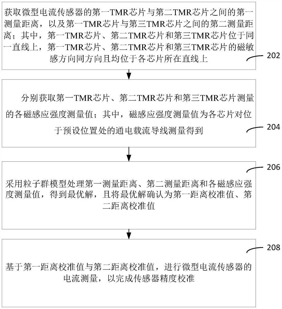
The invention relates to a micro current sensor precision calibration method and device, computer equipment and a storage medium. The method comprises the following steps: processing a first measurement distance and a second measurement distance of three TMR chips and each magnetic induction intensity value measured by each TMR chip for an electrified current-carrying wire located at a preset position by adopting a particle swarm model to obtain an optimal solution, and confirming the optimal solution as a first distance calibration value and a second distance calibration value; and based on the first distance calibration value and the second distance calibration value, carrying out current measurement of the micro current sensor to complete sensor precision calibration. Therefore, an accurate data source is provided for the current measurement of the miniature current sensor, the measurement error of the miniature current sensor is reduced, and the accuracy of the current measurementis improved.

Description

technical field [0001] The present application relates to the technical field of electric power measurement, in particular to a micro current sensor precision calibration method, device, computer equipment and storage medium. Background technique [0002] Current measurement plays an extremely important role in the power industry, providing power systems with the information necessary for metering, control and relay protection. At present, the current measurement of the power system still mainly relies on the traditional electromagnetic current transformer. The disadvantage of this kind of sensor is that it is bulky and expensive. It must prevent the saturation of the iron core. It can only measure AC signals, and the frequency is very low, so it cannot measure high frequency. current. [0003] With the continuous development of the power grid in the direction of intelligence and digitization, the demand for research and development of miniaturization, smart books, and low-...

Claims


Application Information

Patent Timeline
Patent Type & Authority Applications(China)
IPC IPC(8): G01R35/00
CPCG01R35/005
Inventor 李鹏刘仲田兵王志明钟连宏余文辉顾衍璋周柯徐长宝孙宏棣尹旭赵继光李立浧
Owner CHINA SOUTHERN POWER GRID DIGITAL GRID RES INST CO LTD
Learn More