
Combustion furnace and combustor thereof

A burner and furnace technology, which is applied in the directions of gas fuel burners, burners, combustion methods, etc., can solve the problems of increasing processing costs for users and consumers, low combustion efficiency of combustion stoves, and low combustion power of burners, etc. To achieve the effect of stable connection, sufficient combustion, and improved combustion efficiency

Pending Publication Date: 2020-11-20
利邦厨具有限公司
View PDF0 Cites 0 Cited by
  • Summary
  • Abstract
  • Description
  • Claims
  • Application Information

AI Technical Summary

Problems solved by technology

The burner of existing commercial gas cooker mainly comprises combustion chamber, air inlet pipe and air inlet pipe, and air and gas enter combustion chamber through air inlet pipe and inlet pipe respectively, can provide heat for cooking utensils such as frying pan after being ignited; The structure is relatively simple, and it is also very convenient to use, so it is widely used; but the combustion stove with this structure has low combustion efficiency and insufficient combustion, which will cause waste of fuel energy and increase the processing cost of users and consumers; A large amount of flue gas with high carbon content will be produced due to insufficient combustion, causing pollution; and the combustion power of this burner is low, which cannot meet the current use requirements

Method used


Image

  • Combustion furnace and combustor thereof
  • Combustion furnace and combustor thereof
  • Combustion furnace and combustor thereof

Examples


Embodiment 1

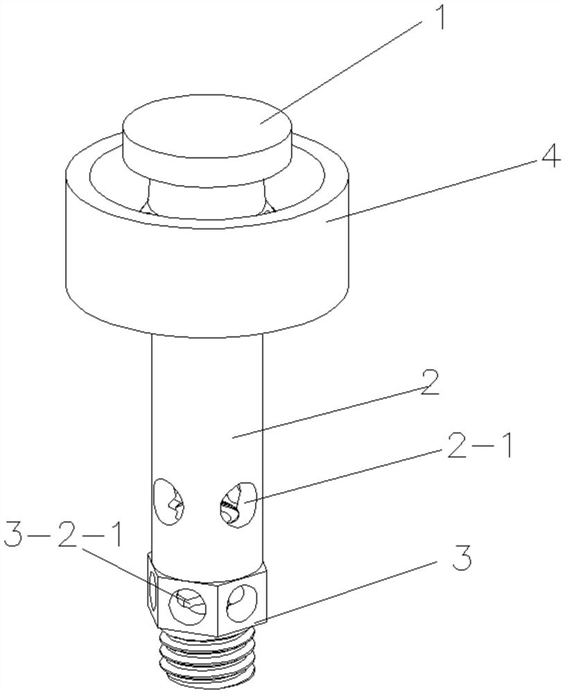
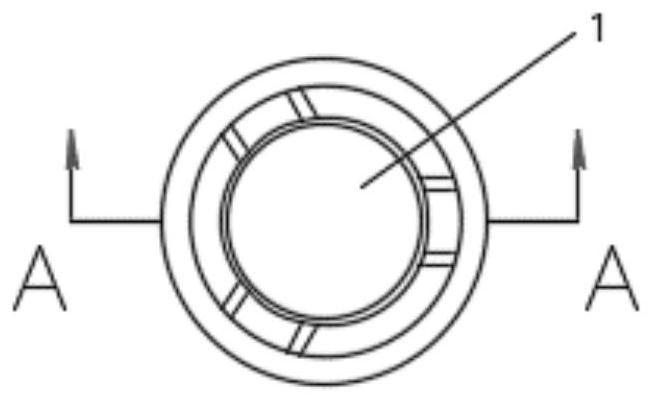
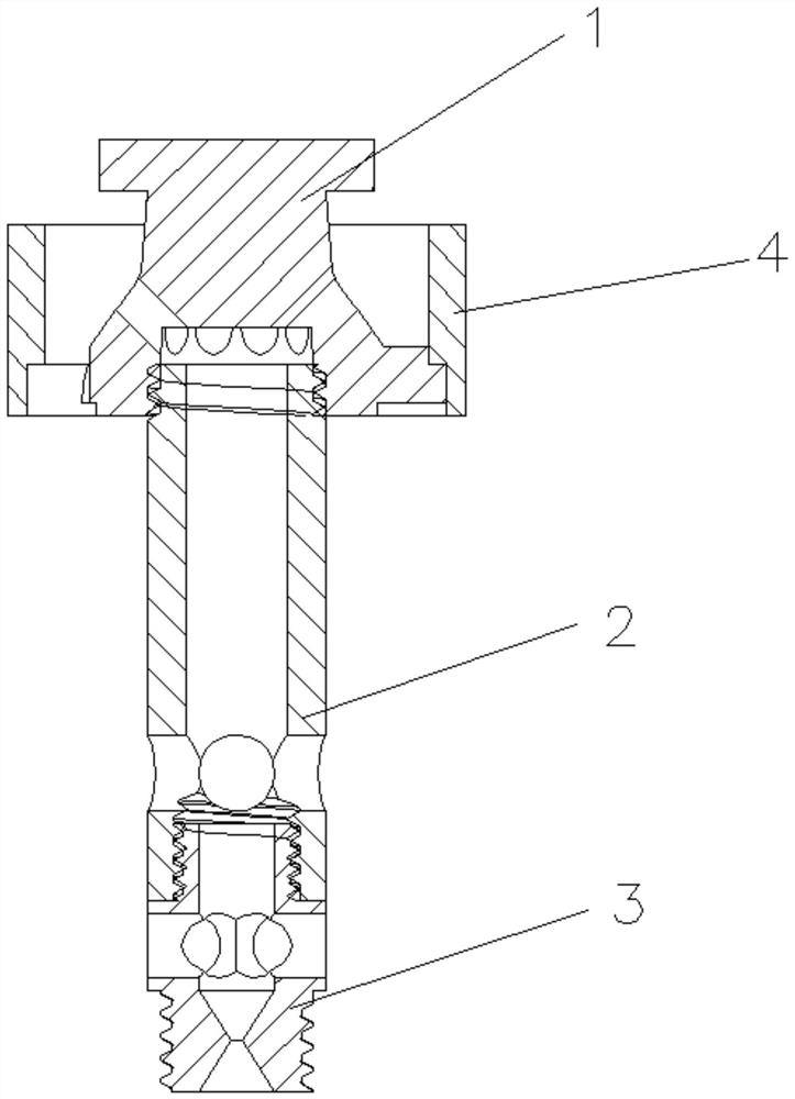
[0041] see Figure 1 to 5 , A combustion furnace of this embodiment includes: a base 5 with a hollow interior, and a burner fixed on the upper end surface of the base 5 and communicating with the inner cavity of the base 5; the burner includes: inner chambers connected sequentially from top to bottom The core 1, the air inlet pipe 2 and the nozzle 3; the side wall of the inner core 1 is provided with at least one first air outlet hole 1-1; the first air outlet hole 1-1 communicates with the air inlet pipe 2; the nozzle 3 conducts up and down, and its upper end is connected with The intake pipe 2 is connected, and the lower end is provided with a first connecting portion 3-1; the first connecting portion 3-1 is provided with an hourglass-shaped channel; the side wall of the nozzle 3 above the first connecting portion 3-1 is provided with at least one An air inlet hole 3-2-1; at least one second air inlet hole 2-1 is provided on the side wall of the air inlet pipe 2; the gas inle...


PUM


Abstract

The invention discloses a combustion furnace and a combustor thereof. The combustor comprises an inner core, an air inlet pipe and a nozzle which are sequentially connected from top to bottom; at least one first air outlet hole is formed in the side wall of the inner core; the first air outlet hole is in communication with the air inlet pipe; the upper part and the lower part of the nozzle are incommunication with each other, the upper end of the nozzle is connected with the air inlet pipe, and the lower end of the nozzle is provided with a first connecting part; an hourglass-shaped channel is formed in the first connecting part; at least one first air inlet hole is formed in the side wall, above the first connecting part, of the nozzle; and at least one second air inlet hole is formed inthe side wall of the air inlet pipe. According to the combustion furnace and the combustor thereof, the channel with the hourglass-shaped longitudinal section is arranged at the gas inlet end, the gas inlet speed is increased, the air inlet holes are formed in the gas inlet pipe and the nozzle correspondingly, air is introduced, gas and air are fully mixed through secondary air inlet, then the combustion efficiency is improved, combustion is sufficient, the carbon content of flue gas is reduced, and pollution is reduced.

Description

Technical field [0001] The invention relates to the field of combustion equipment, in particular to a combustion furnace and its burner. Background technique [0002] Currently, hotels, canteens and central kitchens are all equipped with commercial gas stoves for preparing Chinese food. The burner of the existing commercial gas stove mainly includes a combustion chamber, an air inlet pipe and an air inlet pipe. Air and gas enter the combustion chamber through the air inlet pipe and the air inlet pipe respectively, and can provide heat for cooking utensils such as wok after being ignited; The structure is relatively simple and convenient to use, so it is widely used; but the combustion stove of this structure has low combustion efficiency and insufficient combustion, which will cause waste of fuel energy and increase processing costs for users and consumers; and Due to insufficient combustion, a large amount of flue gas with a higher carbon content will be generated, causing poll...

Claims


Application Information

Patent Timeline
Patent Type & Authority Applications(China)
IPC IPC(8): F23D14/04F23D14/58F23D14/76F24C3/08
CPCF23D14/04F23D14/58F23D14/76F24C3/085
Inventor 黄枫
Owner 利邦厨具有限公司
Learn More