
Metallic vapor deposition preventing structure for hollow cathode

A metal vapor, hollow cathode technology, applied in the direction of using plasma, thrust reverser, machine/engine, etc., can solve the problems of increasing the volume and weight of the hollow cathode, decreasing the insulation performance of ceramics, and failing the life of the hollow cathode, and achieves a simple structure. The effect of easy operation, low cost and broad market application prospects

Active Publication Date: 2020-11-20
BEIJING INST OF CONTROL ENG
View PDF3 Cites 0 Cited by
  • Summary
  • Abstract
  • Description
  • Claims
  • Application Information

AI Technical Summary

Problems solved by technology

When deposited to a certain amount, it will lead to a decrease in the insulation performance of the ceramic, causing a short circuit in the hollow cathode and causing the life of the hollow cathode to fail.
[0006] In the prior art, the distance from the metal vapor to the insulating ceramic can be extended by increasing the axial length of the hollow cathode or increasing the area of ​​the insulating ceramic, so as to delay or even avoid the insulation drop caused by the deposition of metal vapor to meet the service life. requirements; but this will increase the volume and weight of the hollow cathode
This problem is not serious when a hollow cathode is used in a high-power thruster, but in a low-power thruster, it is required to carry out highly integrated and lightweight design of each component, so this problem will be particularly prominent

Method used


Image

  • Metallic vapor deposition preventing structure for hollow cathode
  • Metallic vapor deposition preventing structure for hollow cathode
  • Metallic vapor deposition preventing structure for hollow cathode

Examples


specific Embodiment approach

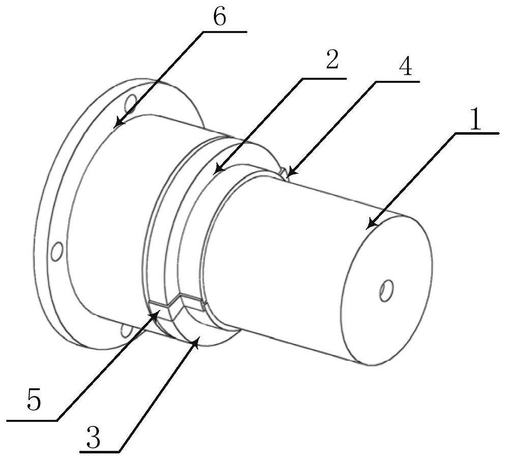
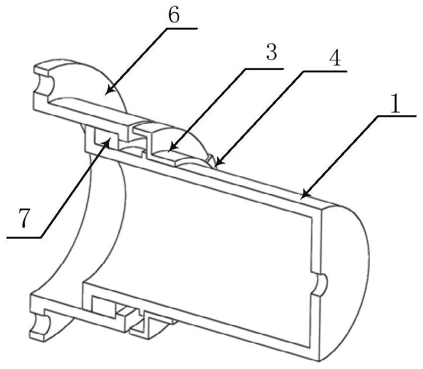
[0051] Fix the mounting flange 6, push the ceramic ring 7 into the mounting flange 6 along the axial direction, so that the two parts fit closely. Then push the contact holding pole shell cylinder 1 into the mounting flange 6 along the axial direction, so that the two parts fit closely. A reliable connection between the mounting flange 6 and the ceramic ring 7 and between the contact holding pole shell cylinder 1 and the ceramic ring 7 is realized by brazing. Push the first half-cylinder 2 and the second half-cylinder 3 in sequence from the second end of the holding pole casing 1 to the first end in the axial direction to the second annular boss position of holding the pole casing 1 , and use spot welding to achieve a stable and reliable connection. The first metal strip 4 and the second metal strip 5 cover the gap in the circumferential direction between the first half cylinder 2 and the second half cylinder 3, and realize stable and reliable connection by spot welding.

[...


PUM

PropertyMeasurementUnit
lengthaaaaaaaaaa
heightaaaaaaaaaa
angleaaaaaaaaaa

Abstract

The invention provides a metallic vapor deposition preventing structure for a hollow cathode. The structure comprises a touch pole shell cylinder, a first semi-circular cylinder, a second semi-circular cylinder, a first metal strip, a second metal strip, a mounting flange and a ceramic ring, wherein the touch pole shell cylinder and the ceramic ring are coaxial and fixed through end surfaces; theceramic ring and the mounting flange are coaxial and fixed through end surfaces; the first semi-circular cylinder and the touch pole shell cylinder are coaxial and fixed through end surfaces; the second semi-circular cylinder and the touch pole shell cylinder are coaxial and fixed through end surfaces; the first semi-circular cylinder and the second semi-circular cylinder are located in the same axial position relative to the touch pole shell cylinder; the first metal strip and the first semi-circular cylinder are coaxial and fixed through end surfaces; the second metal strip and first semi-circular cylinder are coaxial and fixed through end surfaces; the first metal strip and the second metal strip are located in the same axial position relative to the touch pole shell cylinder; and the first metal strip and the second metal strip are uniformly distributed in the circumferential direction.

Description

technical field [0001] The invention relates to an anti-metal vapor deposition structure for a hollow cathode, which is suitable for the hollow cathode and belongs to the technical field of insulation control measures for the hollow cathode of an electric thruster. Background technique [0002] At present, the two mainstream technical directions of spacecraft electric thrusters are Hall propulsion and ion propulsion. Both the Hall thruster and the ion thruster require a hollow cathode to achieve ionization and plume neutralization of ions. [0003] The hollow cathode is mainly composed of a cathode tube, a top plate, an emitter, a heater, and a contact electrode, and is a rotary structure. When the hollow cathode is working, the heater is first supplied with a heating current until the emitter is heated to a certain emission temperature; then the working fluid flows into the hollow cathode tube, and under the action of the flow-limiting hole on the top of the hollow cathode...

Claims


Application Information

Patent Timeline
Patent Type & Authority Applications(China)
IPC IPC(8): F03H1/00
CPCF03H1/0093
Inventor 扈延林毛威吴朋安吴楠胡大为秦宇韩道满山世华李胜军臧娟伟吴耀武李栋
Owner BEIJING INST OF CONTROL ENG
Learn More