Viaduct comprehensive transportation hub ventilation and illumination system

A transportation hub and lighting system technology, applied in the field of ventilation and lighting systems of transportation hubs, can solve problems such as the inability to meet urban life when riding or getting off the bus, expensive central air-conditioning, cumbersome installation and layout, etc., and achieve convenient layout of ventilation system and lighting system , enhance the sense of experience, and reduce manufacturing costs

Active Publication Date: 2020-11-20
上海三维工程建设咨询有限公司 +2
View PDF7 Cites 1 Cited by
  • Summary
  • Abstract
  • Description
  • Claims
  • Application Information

AI Technical Summary

Problems solved by technology

[0002] Traditional bus stations, long-distance transport stations and urban rail transit are all set up independently, so people need to walk a relatively long distance before transferring to the bus station after taking the urban rail transit and then transfer to the bus station, or they need to take a The taxi arrives at the long-distance transport bus station and cannot provide the passengers on the long-distance transport vehicle with the need to get off safely at the viaduct, so that the ride or get off cannot meet the needs of the current fast-paced urban life. At the same time, the existing The ventilation system and lighting system of urban rail transit stations in the technology are set independently, which makes the installation layout more cumbersome, and generally adopts central air-conditioning in multiple centralized locations. However, central air-conditioning is expensive, and the wind output by it Blowing on the human body is relatively obvious, and the wind blown by the ventilation device is relatively strong, so it is quite uncomfortable to blow directly on the human body. Therefore, based on the needs of modern life, it is urgent to solve the above technical problems

Method used


Image

  • Viaduct comprehensive transportation hub ventilation and illumination system
  • Viaduct comprehensive transportation hub ventilation and illumination system
  • Viaduct comprehensive transportation hub ventilation and illumination system

Examples


Embodiment Construction

[0022] The following will clearly and completely describe the technical solutions in the embodiments of the present invention with reference to the accompanying drawings in the embodiments of the present invention. Obviously, the described embodiments are only some, not all, embodiments of the present invention. All other embodiments obtained by persons of ordinary skill in the art based on the embodiments of the present invention belong to the protection scope of the present invention. Example:

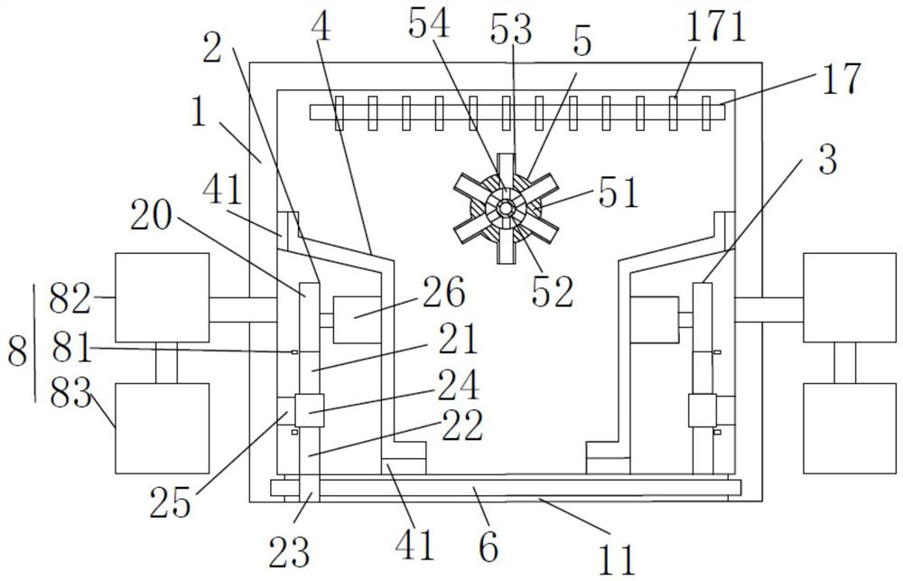
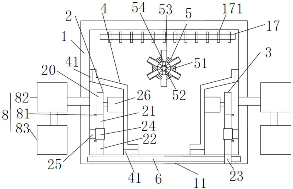
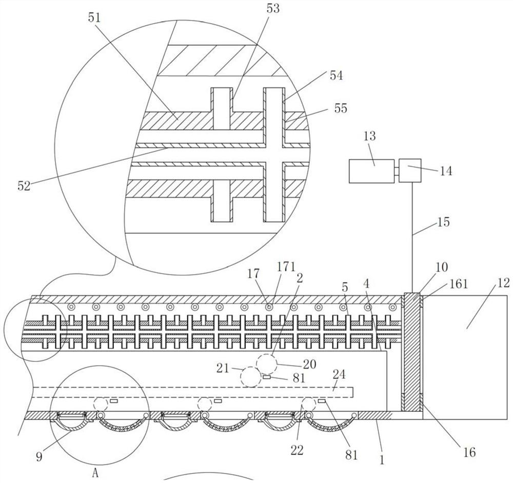
[0023] Such as figure 1 and figure 2 As shown, the ventilation and lighting system of a viaduct integrated transportation hub described in this embodiment includes a viaduct transportation hub integrating railway transportation, bus transportation and long-distance transportation, and an air duct 1 and a fan placed in the indoor space of the viaduct transportation hub. 12 and the control system for controlling the fan 12, the lighting device 9 and the cooling and heating system, t...


PUM


Abstract

The invention relates to a viaduct comprehensive transportation hub ventilation and illumination system. A draught fan is installed at an end opening of an air pipe, and the air pipe is provided witha plurality of air outlets, a plurality of illumination devices, a driving mechanism and a refrigerating and heating system for adjusting the temperature of air in the air pipe; rotating rollers are rotatably mounted on the two corresponding sides of the air outlet, arc-shaped air deflectors are arranged on the rotating rollers, and a plurality of through holes are formed in the arc-shaped air deflectors; a control system is in telecommunication connection with the draught fan, the illumination devices and the refrigerating and heating system, and the driving mechanism is connected with the rotating rollers to enable the two rotating rollers to rotate relatively; when the two arc-shaped air deflectors are completely folded at the air outlet, one arc-shaped air deflector is located on the other arc-shaped air deflector, the lower side face of one arc-shaped air deflector is in complete contact with the upper side face of the other arc-shaped air deflector, the radiuses of the two arc-shaped air deflectors are consistent, and the through holes of the two arc-shaped air deflectors are formed in a staggered mode. Moreover, transfer is convenient; the use and manufacturing cost of ventilation and illumination is reduced, and ventilation and use are comfortable.

Description

technical field [0001] The invention relates to the technical field of a traffic hub ventilation and lighting system applied to a viaduct, in particular to a ventilation and lighting system for a viaduct comprehensive traffic hub. Background technique [0002] Traditional bus stations, long-distance transport stations and urban rail transit are all set up independently, so people need to walk a relatively long distance before transferring to the bus station after taking the urban rail transit and then transfer to the bus station, or they need to take a The taxi arrives at the long-distance transport bus station and cannot provide the passengers on the long-distance transport vehicle with the need to get off safely at the viaduct, so that the ride or get off cannot meet the needs of the current fast-paced urban life. At the same time, the existing The ventilation system and lighting system of urban rail transit stations in the technology are set independently, which makes the...

Claims


Application Information

Patent Timeline
Patent Type & Authority Applications(China)
IPC IPC(8): E01D19/00E01D19/12E04H1/12E01C1/00B08B9/032F16H57/04F21V33/00F24F5/00F24F7/06F24F13/02
CPCB08B9/0321E01C1/002E01D19/00E01D19/12E04H1/1211F16H57/0436F16H57/0456F21V33/006F24F5/0003F24F7/065F24F13/0227F21Y2115/10
Inventor 魏军赵程景亮王国金刘平顾浚灏郑海波夏铭张金龙向长江
Owner 上海三维工程建设咨询有限公司
Why Eureka
Try Eureka