
Large lifting platform

A lifting platform and large-scale technology, applied in the field of elevators, can solve the problems of the influence of the rising speed, the high cost of the lifting platform, and the slow rising speed, and achieve the effect of ensuring the rising speed and reducing the cost of construction.

Pending Publication Date: 2020-11-20
远东中乾(厦门)科技集团股份公司
View PDF1 Cites 2 Cited by
  • Summary
  • Abstract
  • Description
  • Claims
  • Application Information

AI Technical Summary

Problems solved by technology

[0002] Chinese document CN101058394 (application date: April 21, 2006) discloses a safety lifting platform for buried elevators, but in this technical solution, only one lifting device at the central position is used to push the lifting platform. When carrying a lot of goods on the platform, if the goods are not placed centrally, the lifting process of the lifting platform is not easy to be stable, and when a large oil cylinder is used as the lifting device, the rising speed of the piston rod of the large oil cylinder is not fast, and there are also existing lifting platforms. The scheme of stably lifting the platform by adding multiple large oil cylinders, although this type of scheme can improve the lifting stability of the lifting platform, but the rising speed will be greatly affected, and this type of lifting platform usually needs to be equipped with a large oil tank and a high-power motor Only by driving the hydraulic pump can the large oil cylinders work normally, resulting in a higher overall cost of the lifting platform

Method used


Image

  • Large lifting platform
  • Large lifting platform

Examples


Embodiment Construction

[0019] The present invention will be further described below in conjunction with the accompanying drawings and embodiments.

[0020] In describing the present invention, it should be understood that the terms "upper", "lower", "front", "rear", "left", "right", "top", "bottom", "inner", " The orientation or positional relationship indicated by "outside", etc. is based on the orientation or positional relationship shown in the drawings, and is only for the convenience of describing the present invention and simplifying the description, rather than indicating or implying that the referred device or element must have a specific orientation, so as to Specific orientation configurations and operations, therefore, are not to be construed as limitations on the invention.

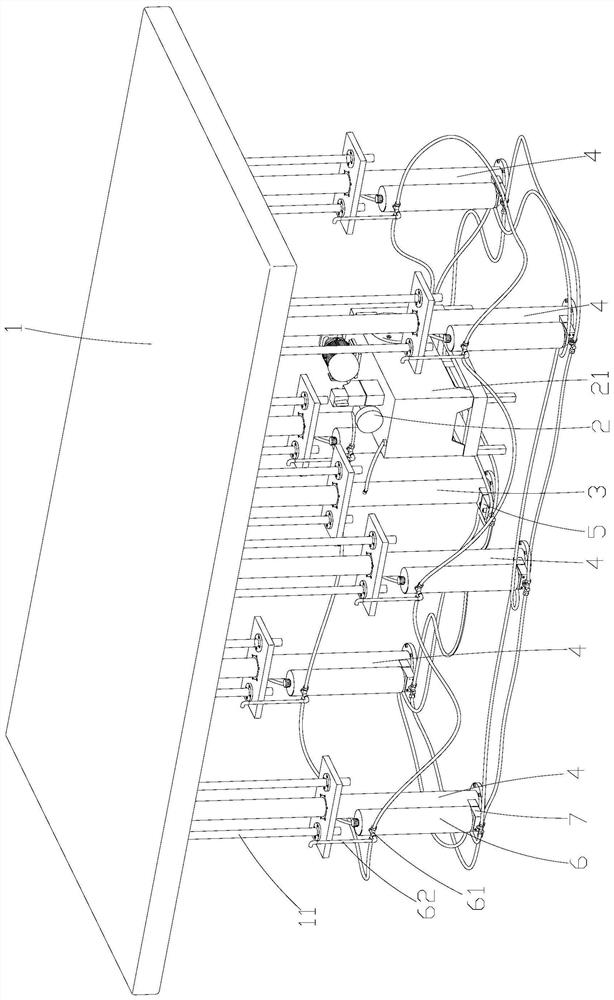
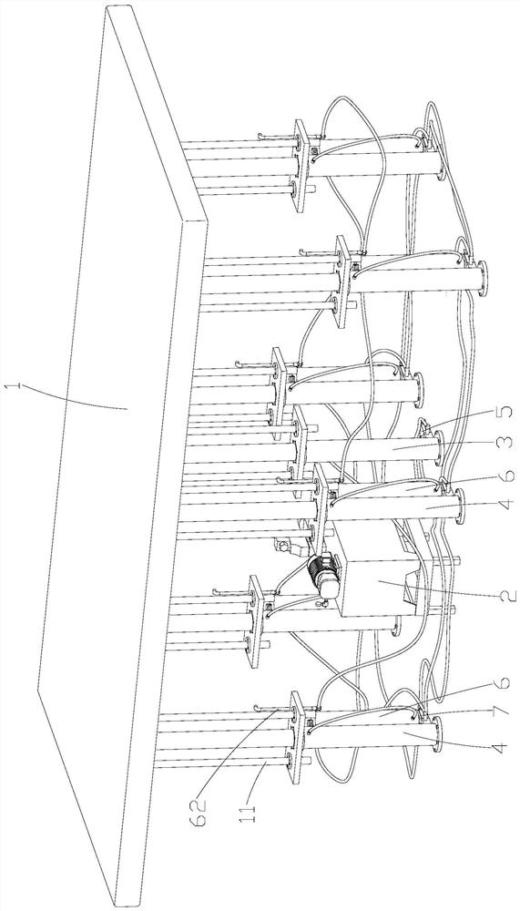
[0021] Please refer to the attached figure 1 , attached figure 2 One embodiment of the present invention provides a large-scale lifting platform, including a lifting platform 1, a liquid-filled oil tank assembly ...


PUM


Abstract

The invention discloses a large lifting platform. The large lifting platform comprises a lifting platform board, a liquid charging fuel tank assembly, a main oil cylinder for jacking up the lifting platform board and a plurality of auxiliary oil cylinders for supporting the lifting platform board, wherein the main oil cylinder is connected to the central position of the bottom of the lifting platform board, the auxiliary oil cylinders are connected to the peripheral positions of the bottom of the lifting platform board, the main oil cylinder communicates with the liquid charging fuel tank assembly, a main oil cylinder hydraulic control one-way valve communicating with the liquid charging fuel tank assembly is arranged at the bottom of the main oil cylinder, each auxiliary oil cylinder is equipped with an auxiliary oil cylinder oil storage tank for charging liquid, and an auxiliary oil cylinder hydraulic control one-way valve is connected between the bottom of each auxiliary oil cylinder and the bottom of the corresponding auxiliary oil cylinder oil storage tank. On the premise of guaranteeing lifting stability of the lifting platform board, only one liquid charging fuel tank assembly is used, overall manufacturing cost of the large lifting platform is reduced, meanwhile, only one main oil cylinder is used for pushing the lifting platform board to ascend, and therefore, the ascending speed of the lifting platform board is guaranteed as far as possible.

Description

technical field [0001] The invention relates to the technical field of lifts, in particular to a large lifting platform. Background technique [0002] Chinese document CN101058394 (application date: April 21, 2006) discloses a safety lifting platform for buried elevators, but in this technical solution, only one lifting device at the central position is used to push the lifting platform. When carrying a lot of goods on the platform, if the goods are not placed centrally, the lifting process of the lifting platform is not easy to be stable, and when a large oil cylinder is used as the lifting device, the rising speed of the piston rod of the large oil cylinder is not fast, and there are also existing lifting platforms. The scheme of stably lifting the platform by adding multiple large oil cylinders, although this type of scheme can improve the lifting stability of the lifting platform, but the rising speed will be greatly affected, and this type of lifting platform usually ne...

Claims


Application Information

Patent Timeline
Patent Type & Authority Applications(China)
IPC IPC(8): B66F7/18B66F7/28B66F3/46B66F3/24F15B21/08
CPCB66F3/24B66F3/46B66F7/18B66F7/28F15B21/087
Inventor 苏炳龙苏双全
Owner 远东中乾(厦门)科技集团股份公司
Learn More