Transformer transfer device

A transfer device and transformer technology, applied in the direction of unloading device, transportation and packaging, containers, etc., can solve the problems of easy damage to the transformer, easy to cause accidents, troublesome transfer process, etc., and achieve the effect of avoiding shaking and preventing back and forth shaking.

Inactive Publication Date: 2020-11-20
蒋兆明
View PDF0 Cites 2 Cited by
  • Summary
  • Abstract
  • Description
  • Claims
  • Application Information

AI Technical Summary

Problems solved by technology

[0002] In the power installation industry, it is often necessary to install transformers in power cabinets, and transformers are large in size and weight, and generally require specific carrying equipment to move the transformers to the installation site. The existing transformers are usually transported by forklifts and lifting devices. It is easy to cause accidents during the process of moving to the carrier and lifting by forklifts and carrier devices, causing greater risks and easily damaging the transformer. Generally, the lifting height of the transformer has corresponding standards, and super-high lifting is strictly prohibited.
[0003] The existing transformer transfer device is relatively complicated in the process of installing and unloading the transformer, requiring more auxiliary equipment and personnel to ensure the fixed loading and unloading of the transformer, and the transfer process is more troublesome

Method used


Image

  • Transformer transfer device
  • Transformer transfer device
  • Transformer transfer device

Examples


Embodiment 1

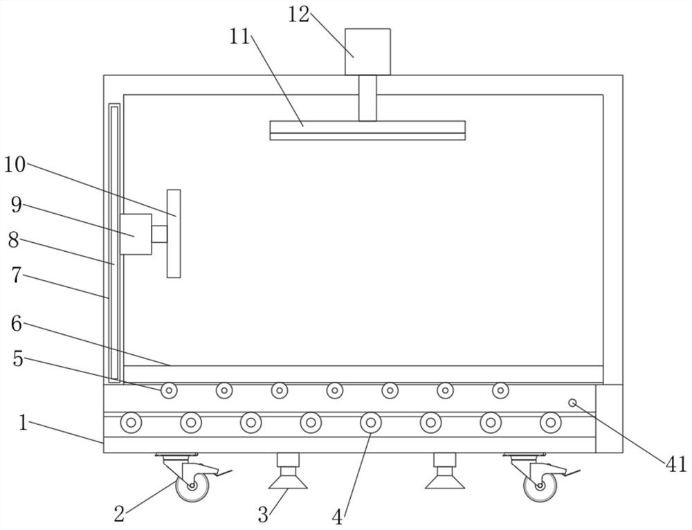
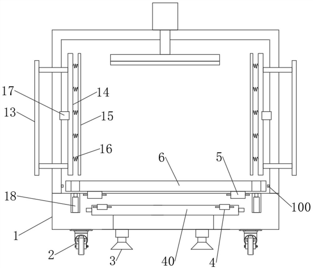
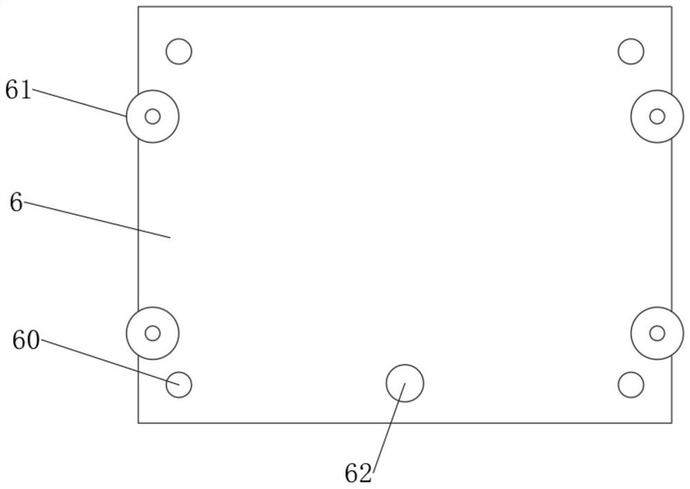
[0030] Such as Figure 1-6 As shown, a transformer transfer device includes a housing 1, the bottom of the housing 1 is provided with a universal wheel 2, the bottom of the housing 1 is provided with an inner panel 40, and the two ends of the inner panel 40 A sliding column 41 is provided, and a chute 42 is provided on the housing 1. The inner panel 40 is slidably connected to the chute 42 through the sliding column 41. The chute 42 is set in a J shape, and the inner panel 40 The bottom of 40 is provided with a hydraulic seat 3, the surface of the inner panel 40 is provided with a first roller 4, the surface of the bottom of the housing 1 is provided with a second roller 5, and a placement plate is arranged on the second roller 5 6. The placement plate 6 is provided with a fixing hole 60, the bottom plate of the housing 1 is embedded with a telescopic column 18, and the telescopic column 18 is fixedly installed with the bottom of the housing 1, and the telescopic column 18 is ...

Embodiment 2

[0039] This embodiment is a further improvement and limitation of embodiment 1 on the basis of embodiment 1.

[0040] A transformer transfer device, including all parts in embodiment 1, also includes:

[0041] Further, a first hydraulic cylinder 9 is movably installed on the front cover plate 8, the first hydraulic cylinder 9 is connected to the first fixing plate 10, and the top of the housing 1 is provided with a second hydraulic cylinder 12, The second hydraulic cylinder 12 is connected with the second fixing plate 11 .

[0042]Specifically, the first hydraulic cylinder 9 is installed through the front cover plate 8, the front end of the transformer is fixed by the first hydraulic cylinder 9 and the first fixing plate 10, and the top of the transformer is fixed by the second hydraulic cylinder 12 and the second fixing rod. fixed.

[0043] Further, the left and right sides of the housing 1 are provided with mounting brackets 13, the mounting brackets 13 are plugged into th...


PUM


Abstract

The invention discloses a transformer transfer device, relates to the technical field of transformer transport, and mainly solves the problems that an existing transformer carrying tool is complex touse and high in cost. The device comprises a shell body, wherein universal wheels are arranged at the bottom of the shell body; an embedded plate is arranged at the bottom of the shell body; slide columns are arranged at the two ends of the embedded plate; a slide groove is formed in the shell body; the embedded plate is slidably connected with the slide groove through the slide columns; the slidegroove is configured to be J-shaped; a hydraulic seat is arranged at the bottom of the embedded plate; a first roller is arranged on the surface of the embedded plate; a second roller is arranged onthe surface of the bottom of the shell body; a placement plate is arranged on the second roller; a fixing hole is formed in the placement plate; a telescopic column is installed on a bottom plate of the shell body in an inlaying manner; the telescopic column and the bottom of the shell body are fixedly installed; the telescopic column and the fixing holes are mutually matched; pulleys are arrangedat the two sides of the placement plate; and a push-pull hole is formed in front of the placement plate.

Description

technical field [0001] The invention relates to the technical field of transformer transportation, in particular to a transformer transfer device. Background technique [0002] In the power installation industry, it is often necessary to install transformers in power cabinets, and transformers are large in size and weight, and generally require specific carrying equipment to move the transformers to the installation site. The existing transformers are usually transported by forklifts and lifting devices. It is easy to cause accidents during the process of moving to the carrier and lifting by forklifts and carrier devices, causing greater risks and easily damaging the transformer. Generally, there are corresponding standards for the lifting height of transformers, and ultra-high lifting is strictly prohibited. [0003] The existing transformer transfer device is relatively complicated in the process of installing and unloading the transformer, requiring more auxiliary equipme...

Claims


Application Information

Patent Timeline
Patent Type & Authority Applications(China)
IPC IPC(8): B65D25/52B65D25/10B65D25/24B65D81/07B65D81/05B65D85/68
CPCB65D25/10B65D25/101B65D25/24B65D25/52B65D81/05B65D81/07B65D85/68
Inventor 蒋兆明
Owner 蒋兆明
Why Eureka
Try Eureka