Eureka AIR delivers breakthrough ideas for toughest innovation challenges, trusted by R&D personnel around the world.

Glass grinding head motor with brand-new protective structure

A protective structure and glass technology, which is applied in the direction of machine tools, grinders, electromechanical devices, etc., which are suitable for grinding the edge of workpieces, and can solve the problems of slow outflow of mixed liquid, stuck motor, corrosion damage, etc.

Pending Publication Date: 2020-11-20
SHANGHAI CDQC ELECTRIC
View PDF1 Cites 0 Cited by
  • Summary
  • Abstract
  • Description
  • Claims
  • Application Information

AI Technical Summary

Problems solved by technology

[0004] In the structure of the above-mentioned utility model patent, although the combination of the drainage gap and the inclined conical water retaining surface of the stainless steel connector is adopted, the water entering the waterproof gap can be discharged in time to a certain extent, but considering the glass grinding environment The characteristics of the mixed liquid of water and glass powder and the defects of the above-mentioned waterproof structure lead to the mixed liquid entering the waterproof gap only flowing to the bottom end of the stainless steel connecting piece before it can be separated from the stainless steel connecting piece and dripped to the grinding wheel seat before being thrown out. The outflow speed of the mixed liquid is too slow, and the mixed solution is easy to precipitate, solidify and accumulate on the front side of the front end cover, and the front end cover is generally made of iron material, the mixed liquid will corrode and damage it, and then enter the inside of the motor, causing the motor to start and freeze

Method used


Image

  • Glass grinding head motor with brand-new protective structure
  • Glass grinding head motor with brand-new protective structure
  • Glass grinding head motor with brand-new protective structure

Examples


Embodiment Construction

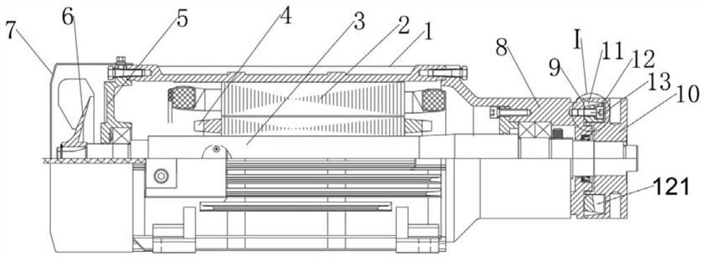
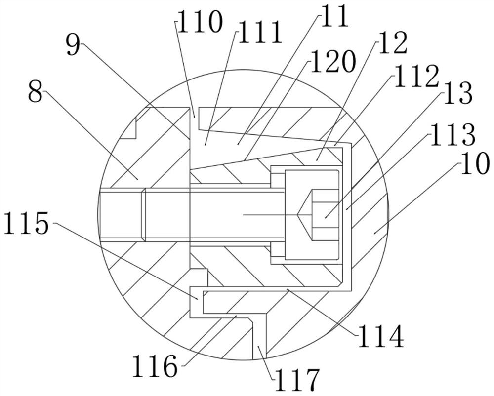
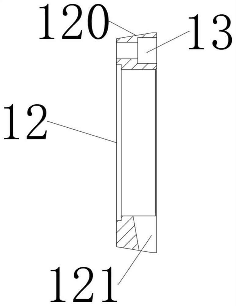
[0012] Depend on Figure 1 to Figure 4 It can be seen that the glass grinding head motor of the present invention mainly includes a housing 1 , a stator core 2 with windings disposed in the housing 1 , and a rotor 4 located in the stator core 2 and supported by the motor shaft 3 . The front and rear ends of the housing 1 are connected with a front end cover 8 and a rear end cover 5, and the front end and the rear end of the motor shaft 3 pass through the front end cover 8 and the rear end cover 5 respectively and are respectively fixed with a grinding wheel seat 10 and a fan. 6. The wind cover 7 covering the fan 6 is also fixed on the rear end cover 5 . The outer edge of the front end face of the front end cover 8 is provided with an end face step 9, and the end face step 9 is fixed with a protective ring 12, and the protective ring 12 is fixed on the end face step 9 by three hexagon socket head cap screws 13. There is a protective gap 11 between the grinding wheel holder 10 ...


PUM


Abstract

The invention relates to a glass grinding head motor with a brand-new protective structure. The motor comprises a housing, an iron core located in the housing, and a rotor located in the iron core andsupported by a motor rotating shaft, wherein the front end of the housing is connected with a front end cover, the front end head of the motor rotating shaft penetrates through the front end cover, agrinding wheel seat is fixed to the front end head of the motor rotating shaft, a protective gap is arranged between the matching surface of the front end cover and the grinding wheel seat, an end face step is arranged at the outer edge of the front end surface of the front end cover, a protective ring is fixedly arranged in the end face step, the rear part of an outer ring of the protective ringis an oblique conical water retaining surface, the front part is in a horizontal plane, an inner ring of the protective ring is in a horizontal plane, the front end surface of the protective ring isa vertical surface, a gap is arranged at the bottom of the protective ring, and the gap is located on the front end surface of the protective ring. By adopting the structure, mixed liquid can quicklydrop and can be quickly thrown out, and at the same time, when glass powder and other precipitated solids appear in the protective gap, the gap can serve as a temporary storage space, so that the motor is not liable to get stuck in a short time.

Description

technical field [0001] The invention relates to the field of grinding head motors, in particular to a glass grinding head motor with a new protective structure. Background technique [0002] The grinding head motor is mainly used in the glass deep processing industry for grinding glass corners. Due to the special requirements for working conditions and performance, there are higher requirements for the life and precision of the grinding head motor. The effect of the waterproof and dustproof function of the grinding head motor is directly related to the service life and accuracy of the grinding head motor. However, it is obviously difficult to maintain high-precision, stable operation and long life under such high-temperature, high-humidity, high-dust, and high-load conditions. These difficulties mainly come from the mechanical part of the motor, especially whether the protective structure at the mating surface of the motor grinding wheel seat and the front end cover is scie...

Claims


Application Information

Patent Timeline
IPC IPC(8): B24B9/08B24B55/00H02K5/10H02K7/14
CPCB24B9/08B24B55/00H02K5/10H02K7/14
Inventor 陈仙根陆思远
Owner SHANGHAI CDQC ELECTRIC
Why Eureka
Eureka Blog
Learn More