Full-band high-tone-quality thin loudspeaker with sound beam and sound tunnels

A loudspeaker, full-band technology, applied in the field of loudspeakers, can solve problems such as unfavorable sound wave vibration, unreasonable structural design, and inability to shine in the high-pitched area, and achieve the effect of improving timbre and sound quality, highlighting substantive features, and making significant technological progress.

Pending Publication Date: 2020-11-17
SUZHOU LI YUE MUSICAL INSTR CO LTD
View PDF0 Cites 1 Cited by
  • Summary
  • Abstract
  • Description
  • Claims
  • Application Information

AI Technical Summary

Problems solved by technology

[0003] The common problem of traditional thin speakers is that the speaker has an inherent resonant frequency when making sound. After exceeding a certain range of the resonant frequency area, the high-pitched area cannot be bright, and the low-pitched area is not thick and mellow enough.
Bass must be achieved through a dedicated woofer, and treble must be achieved through a dedicated tweeter, that is, the timbre is proportional to the number of speakers, and it is impossible to achieve full-range high-quality timbre through a single speaker
The main reason is that the current loudspeaker diaphragm cannot meet the good broadband vibration from the high-pitched range to the low-pitched range, that is, it cannot adapt to the resonance and vibration of the wide-ranging frequency changes in the high-pitched, mid-range, and low-pitched ranges at the same time.
In summary, the structural design of traditional thin speakers is unreasonable, which is not conducive to the good sound wave vibration of the diaphragm from the high-pitched range to the low-pitched range.

Method used


Image

  • Full-band high-tone-quality thin loudspeaker with sound beam and sound tunnels
  • Full-band high-tone-quality thin loudspeaker with sound beam and sound tunnels
  • Full-band high-tone-quality thin loudspeaker with sound beam and sound tunnels

Examples


Embodiment

[0054] Embodiments: The present invention will be clearly described below with drawings and detailed descriptions. After any person skilled in the art understands the embodiments of the present invention, they can be changed and modified by the techniques taught in the present invention without departing from the present invention. The spirit and scope of the invention.

[0055] As used herein, "connection" or "arrangement" can mean that two or more components or devices are in direct physical contact with each other, or that they are in indirect physical contact with each other, or that two or more components or devices are in mutual operation. or action.

[0056] As used herein, "comprising", "comprising", "having" and the like are all open terms, meaning including but not limited to.

[0057] Regarding the terms used in this article, unless otherwise specified, generally have the ordinary meaning of each term used in this field, in the content of this case and in the speci...


PUM


Abstract

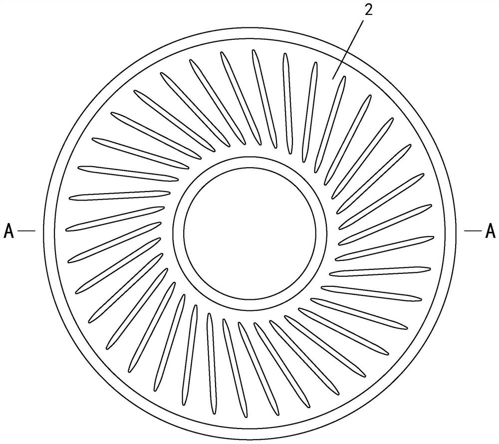
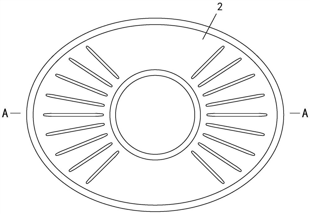
The invention discloses a full-band high-tone-quality thin loudspeaker with a sound beam and sound tunnels. The loudspeaker comprises a voice coil and a vibrating diaphragm; the diaphragm is dish-shaped, the outer edge of the diaphragm is combined with the loudspeaker outer frame, and the inner edge is combined with the upper end of the voice coil; a bridge type sound beam is erected on at least one side surface of the vibrating diaphragm, is annular and is positioned on the outer side of the upper end of the voice coil; the surface of the vibrating diaphragm is provided with at least two grooves, and the grooves are arranged in a radial manner, and equally divide the surface of the vibrating diaphragm at the outer side of the bridge type sound beam into a plurality of resonance regions; each groove transversely penetrates through the bridge type sound beam, and the length direction of the grooves is perpendicular to the bridge type sound beam; and the grooves are concavely arranged onthe surface of the vibrating diaphragm to form sound tunnels. According to the invention, the vibrating diaphragm is changed from the original free vibration mode to the current standard vibration mode, and the problems that the high-pitch area of the loudspeaker cannot be lighted and the low-pitch area is thick and round are solved from the angles of vibration, resonance and sound production. The practice proves that: the improved design scheme has outstanding substantive features and remarkable technical progress, and is suitable for popularization and application. and an obvious technicaleffect is achieved.

Description

technical field [0001] The invention relates to a loudspeaker, in particular to a full-frequency high-quality thin loudspeaker with a sound beam and a sound tunnel. The thin loudspeaker can be applied to electronic products such as earphones, headsets, mobile phones, tablet computers, and notebook computers. Background technique [0002] A loudspeaker (also known as a horn) is a device that converts electrical signals into acoustic signals, such as Figure 1~8 As mentioned above, a traditional thin speaker is usually composed of a voice coil 1, a diaphragm 2, a magnet, and a magnetically conductive structure (not shown in the figure). When the speaker is working, the currents output by the amplifier are converted into sound waves through frequency waves, and the output energy is increased through the promotion of power, and the voice coil 1 is moved under the action of the magnetic field, and the voice coil 1 is connected to the diaphragm 2 and drives the diaphragm 2 to vibr...

Claims


Application Information

Patent Timeline
IPC IPC(8): H04R9/06H04R9/04H04R7/18H04R7/12
CPCH04R9/06H04R9/045H04R7/12H04R7/18
Inventor 金海鸥吴念博何新喜朱信智李碧英杨萍
Owner SUZHOU LI YUE MUSICAL INSTR CO LTD
Why Eureka
Try Eureka