Implantable antenna work site performance test method and system

A technique for field testing on the job site, applied in the direction of electromagnetic field characteristics, antenna radiation patterns, measuring devices, etc.

Pending Publication Date: 2020-11-17
HUNAN UNIV
View PDF0 Cites 2 Cited by
  • Summary
  • Abstract
  • Description
  • Claims
  • Application Information

AI Technical Summary

Problems solved by technology

But how to ensure the reliability of the test and suppress the multipath effect of the signal becomes a problem

Method used


Image

  • Implantable antenna work site performance test method and system
  • Implantable antenna work site performance test method and system
  • Implantable antenna work site performance test method and system

Examples


Embodiment Construction

[0050] In order to make the purpose, technical solution and advantages of the present application clearer, the present application will be further described in detail below in conjunction with the accompanying drawings and embodiments. It should be understood that the specific embodiments described here are only used to explain the present application, and are not intended to limit the present application.

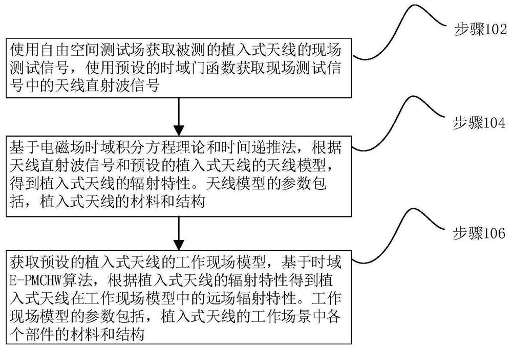
[0051] In one embodiment, such as figure 1 As shown, a method for testing the field performance of an implanted antenna is provided, including the following steps:

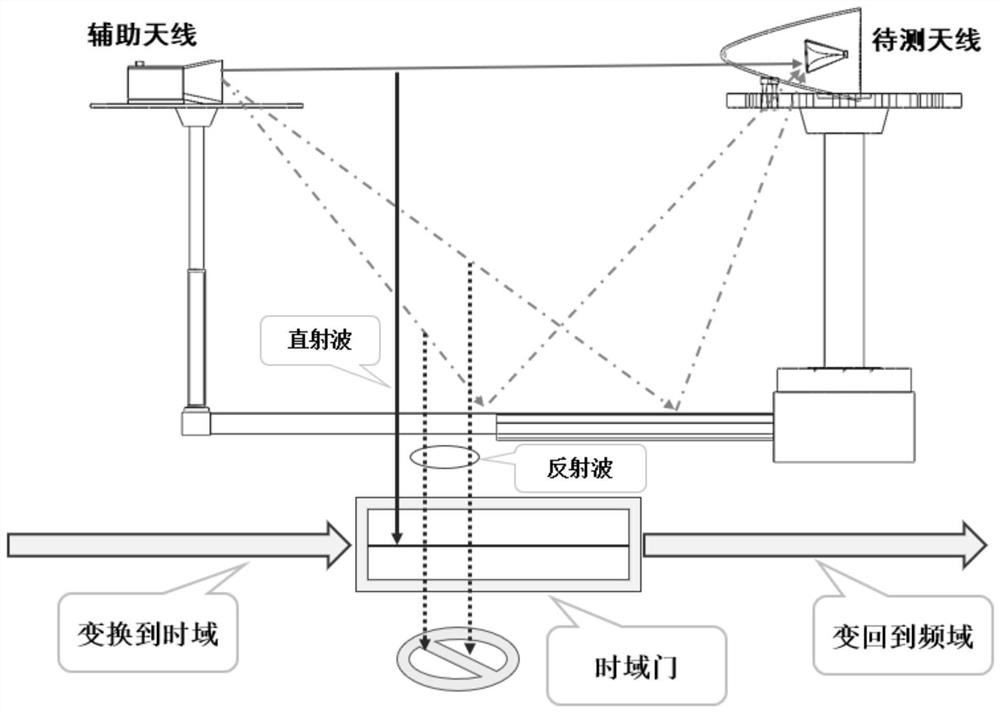
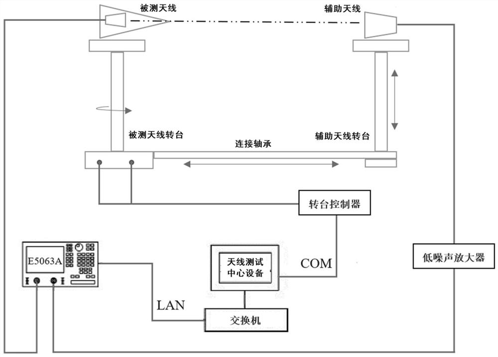
[0052] Step 102, using a free space test field to obtain field test signals of the implanted antenna under test, and using a preset time-domain gate function to obtain antenna direct wave signals in the field test signals.

[0053] Due to the characteristics of the implanted antenna, the implanted antenna tested in this application refers to the whole formed by installing the antenna itself in the implanted p...


PUM


Abstract

The invention relates to an implantable antenna work site performance test method and system. The method comprises the following steps: acquiring a field test signal of a tested implantable antenna byusing a free space test field, acquiring an antenna direct wave signal in the field test signal by using a time domain gate function, and according to the antenna direct wave signal and an antenna model of the implantable antenna based on an electromagnetic field time domain integral equation theory and a time recursion method, obtaining the radiation characteristic of the implantable antenna; and based on a time domain EPMCHW algorithm, obtaining the far-field radiation characteristics of the implantable antenna in the work site model according to the radiation characteristics of the implantable antenna. According to the method, the influence of the equipment where the implantable antenna is located and the application environment of the implantable antenna on the antenna radiation performance is considered, the far-field radiation characteristics of the implantable antenna in the specific application environment are obtained on the basis, targeted performance testing can be carriedout on the implantable antenna in the working site environment, and a more accurate testing result is obtained.

Description

technical field [0001] The present application relates to the technical field of antenna testing, in particular to a method and system for testing the performance of an implanted antenna at a working site. Background technique [0002] With the improvement of equipment integration and integration requirements, more and more equipment in electronic information systems such as vehicles, aircraft, ships, and satellites begin to use implanted antennas. Unlike stand-alone antennas that stick out of the device, implanted antennas are shaped for a specific device and are often embedded or wrapped to closely fit the device. Therefore, when testing the implanted antenna, it is necessary to start from the perspective of the whole device, and it is necessary to consider the influence of the application environment of the device on the performance of the implanted antenna. [0003] Due to the close relationship between the implanted antenna and the corresponding equipment and applicati...

Claims


Application Information

Patent Timeline
IPC IPC(8): G01R29/08G01R29/10
CPCG01R29/0871G01R29/10
Inventor 李高升冯杨潘少鹏陈攀亓琳
Owner HUNAN UNIV
Why Eureka
Try Eureka