
Soldering station mechanism for battery assembly

A technology for battery components and soldering stations, applied in welding equipment, auxiliary welding equipment, welding/cutting auxiliary equipment, etc., can solve problems such as virtual welding, missing welding, and high temperature resistance, and achieve the effect of wide applicability

Pending Publication Date: 2020-11-17
SUZHOU SHENGCHENG SOLAR EQUIP
View PDF0 Cites 0 Cited by
  • Summary
  • Abstract
  • Description
  • Claims
  • Application Information

AI Technical Summary

Problems solved by technology

[0002] During the production process of solar modules, two groups of cells need to be welded together, each group includes six strings of cells, three kinds of welding flow rods are needed to weld these cells together, the electrodes need to be placed on the welding table first, and then The cells are placed on top of it for welding. In order to ensure the position of the electrodes, suction cups are often used to hold the electrodes. However, the suction cups are made of rubber and are not resistant to high temperatures. High temperatures are easy to damage the suction cups during welding. For products of different sizes, the positions of two adjacent electrodes are different. , the ordinary structure is difficult to meet the above elastic requirements, the thickness of the electrode is 0.2 ~ 0.4mm, which is relatively thin, the welding head is not flat, and it is easy to have virtual welding and missing welding during the welding process. Based on the above defects and deficiencies, it is necessary to The existing technology is improved, and a welding station mechanism for battery components is designed

Method used


Image

  • Soldering station mechanism for battery assembly
  • Soldering station mechanism for battery assembly
  • Soldering station mechanism for battery assembly

Examples


Embodiment Construction

[0015] The preferred embodiments of the present invention will be described in detail below in conjunction with the accompanying drawings, so that the advantages and features of the invention can be more easily understood by those skilled in the art, so as to define the protection scope of the present invention more clearly.

[0016] see Figure 1 to Figure 4 , the embodiment of the present invention includes:

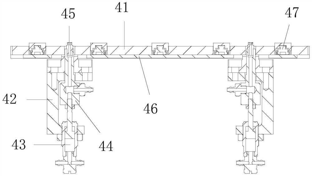
[0017] A soldering station mechanism for a battery assembly, the soldering station mechanism for a battery assembly includes a linear module 1, a moving linear slide rail 2, a moving frame 3 and a soldering station assembly 4, the linear module 1 and the following linear slide The rails 2 are set in parallel, the sliding block of the linear module 1 is equipped with a moving frame 3, the other end of the moving frame 3 is set on the slider of the following linear slide rail 2, and the welding frame with adjustable positions is installed in an array on the moving frame ...


PUM


Abstract

The invention discloses a soldering station mechanism for a battery assembly. The soldering station mechanism for the battery assembly comprises a linear module, a follow-up linear sliding rail, a moving frame and soldering station assemblies, wherein the linear module and the follow-up linear sliding rail are arranged in parallel; the moving frame is installed on a sliding block of the linear module; the other end of the moving frame is arranged on a sliding block of the follow-up linear sliding rail; the position-adjustable soldering station assemblies are installed on the moving frame in anarray mode; horizontally-arranged adjusting holes are formed in the moving frame at equal intervals; and screws penetrate through the adjusting holes and then are locked onto the soldering station assemblies. By means of the mode, the soldering station is compact in structure, stable in operation, and capable of guaranteeing the stability of a welding rod; a rubber sucking disc downwards moves and retreats so as to be prevented from being damaged by high-temperature welding; the positions of each two adjacent soldering station assemblies is adjustable so as to be capable of being matched withproducts of different sizes, so that the applicability is wide; and a welding point floating structure is arranged in a floating mode, so that a welding head is ensured to make close contact with a welding point without damaging a product.

Description

technical field [0001] The invention relates to the technical field of solar module production, in particular to a welding station mechanism for a battery module. Background technique [0002] During the production process of solar modules, two groups of cells need to be welded together, each group includes six strings of cells, three kinds of welding flow rods are needed to weld these cells together, the electrodes need to be placed on the welding table first, and then The cells are placed on top of it for welding. In order to ensure the position of the electrodes, suction cups are often used to hold the electrodes. However, the suction cups are made of rubber and are not resistant to high temperatures. High temperatures are easy to damage the suction cups during welding. For products of different sizes, the positions of two adjacent electrodes are different. , the ordinary structure is difficult to meet the above elastic requirements, the thickness of the electrode is 0.2 ...

Claims


Application Information

Patent Timeline
IPC IPC(8): B23K37/04B23K37/00B23K101/36
CPCB23K37/00B23K37/0461B23K2101/36
Inventor 杨晨黄曰龙贺红峰宋家裕
Owner SUZHOU SHENGCHENG SOLAR EQUIP
Learn More