
Motor rotor paint dipping device and using method thereof

A technology of motor rotor and dipping paint, applied in electromechanical devices, manufacturing motor generators, electrical components, etc., can solve the problems of poor dipping effect, low efficiency and narrow application range.

Active Publication Date: 2020-11-13
绍兴市希多电机有限公司
View PDF11 Cites 4 Cited by
  • Summary
  • Abstract
  • Description
  • Claims
  • Application Information

AI Technical Summary

Problems solved by technology

[0003] After the rotor is produced, it needs to be dipped in paint. The rotor dipped in paint can fill the gaps and air layers of its coils. After curing, it can form a continuous and flat paint film on the surface of the dipped paint windings and components, and make the windings bonded into a whole, improving The coil insulation and curing structure are improved, and the moisture resistance, heat resistance and mechanical strength of the electric motor are enhanced. The traditional motor rotor impregnation device has the following defects: 1. Only the motor rotor of the same specification can be impregnated, and it cannot be realized. Simultaneous impregnation of motor rotors of different specifications has a narrow scope of application; 2. Only one motor rotor can be impregnated with paint, which is inefficient, time-consuming and labor-intensive; 3. Workers are required to manually reverse or not reverse the motor rotor , not only the dipping effect is not good, but also the workers work in a high temperature environment, which is undoubtedly harmful to the workers; 4. The motor rotor after dipping needs to be transferred and then air-dried, which not only wastes time, but also increases the work of the workers amount, so we propose a motor rotor dipping device and its use method to solve the above-mentioned problems

Method used


Image

  • Motor rotor paint dipping device and using method thereof
  • Motor rotor paint dipping device and using method thereof
  • Motor rotor paint dipping device and using method thereof

Examples


Embodiment 1

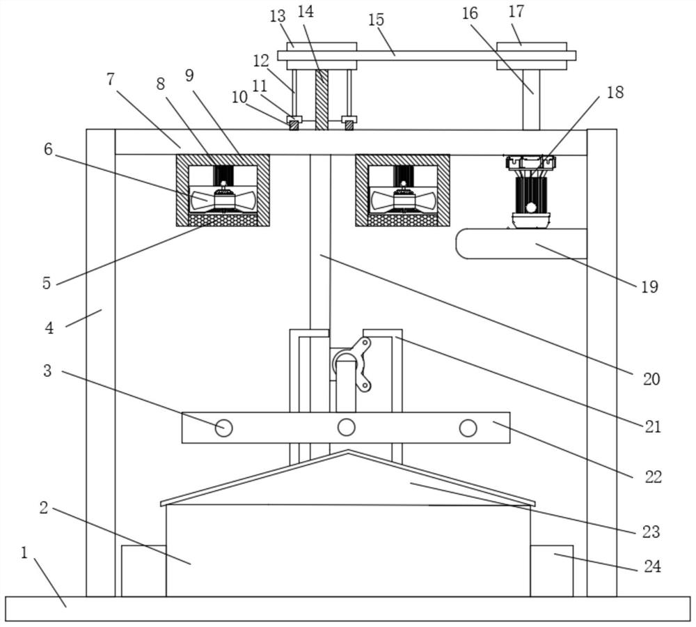
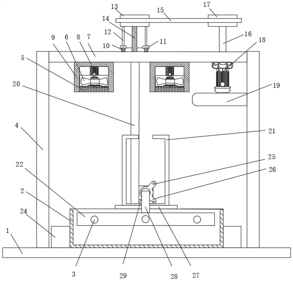
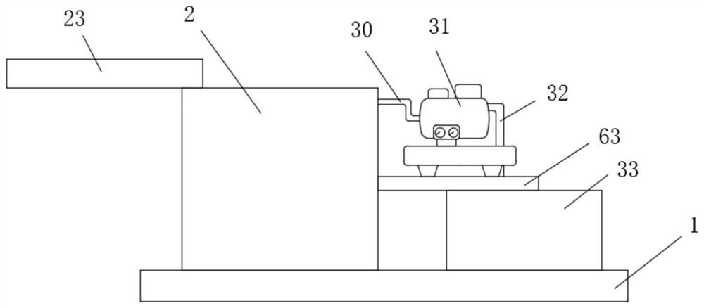
[0051] Embodiment one: if Figure 1-15 As shown, a motor rotor impregnating device includes a fixed base 1 and a motor rotor body 46, the top of the fixed base 1 is fixedly connected with two symmetrically arranged support columns 4, and the top of the side of the two support columns 4 close to each other is fixed The same first mounting plate 7 is connected, and the bottom of the first mounting plate 7 has an air-drying assembly for air-drying the rotor body 46 of the motor. The top of the fixed base 1 is fixedly connected with a paint dipping box 2, and one side of the paint dipping box 2 is placed separately. There is a steering assembly for turning over the motor rotor body 46 and a paint touch-up assembly for replenishing the paint dipping box 2. The top of the first mounting plate 7 is provided with a lifting assembly for lifting the motor rotor body 46. One side of the lifting assembly A placement assembly for placing the motor rotor body 46 is fixedly connected.

[00...

Embodiment 2

[0069] Embodiment two: if Figure 16 As shown, a motor rotor impregnating device, the difference between this embodiment and Embodiment 1 is: the top of the fixed base 1 is fixedly connected with a sealing cover 58, and one side of the sealing cover 58 is provided with a transparent window 62 and a door opening. A door 57 is hinged inside, a sealing ring 61 is arranged between the door 57 and the inlet and outlet, a handle 59 is arranged on one side of the door 57, a vacuum pump 60 is arranged on the top of the fixed base 1, and the vacuum pump 60 communicates with the sealing cover 58, and the support column 4. The first mounting plate 7 and the paint dipping box 2 are all located in the sealing cover 58. During the paint dipping operation, the vacuum pump 60 can be started, so that the inside of the sealing cover 58 is in a vacuum state, so that the motor rotor body 46 can be better dipped in paint. After the dipping operation is completed, close the vacuum pump 60, open the...


PUM


Abstract

The invention discloses a motor rotor paint dipping device. The motor rotor paint dipping device comprises a fixed base and a motor rotor body, and the top of the fixed base is fixedly connected withtwo symmetrically-arranged supporting columns. The tops of the sides, close to each other, of the two supporting columns are fixedly connected with the same first mounting plate; an air drying assembly used for air drying of the motor rotor body is arranged at the bottom of the first mounting plate, a paint dipping box is fixedly connected to the top of the fixed base, and a steering assembly usedfor turning over the motor rotor body and a paint supplementing assembly used for supplementing paint to the paint dipping box are placed on one side of the paint dipping box. The present invention further discloses a using method. The beneficial effects of the motor rotor paint dipping device and the using method thereof are that: through clamping of a placement assembly, motor rotors of different specifications can be subjected to paint dipping at the same time, then paint dipping operation is achieved through the lifting assembly, after paint dipping is completed, air drying is conducted through the air drying assembly, overturning is conducted through a steering assembly, the two faces of each motor rotor can be air-dried, efficiency is improved, the workload of workers is reduced, operation is convenient, and practicability is high.

Description

technical field [0001] The invention relates to the technical field of motor rotors, in particular to a motor rotor paint dipping device and a method for using the same. Background technique [0002] Rotor refers to the rotating body supported by bearings, mostly the main rotating parts in power machinery and working machinery. Objects such as optical discs that do not have their own axis of rotation can be considered a rotor when rigidly connected or attached. When the rotor rotates at certain speeds, it will deform greatly and cause resonance. The speed at which resonance is caused is called the critical speed of the rotor. In engineering, a rotor whose working speed is lower than the first-order critical speed is called a rigid rotor, and a rotor whose working speed is greater than the first-order critical speed is called a flexible rotor. Since the rotor rotates at a high speed, it needs to be balanced. Static balancing is mainly used to balance the inertial force of ...

Claims


Application Information

Patent Timeline
Patent Type & Authority Applications(China)
IPC IPC(8): H02K15/12
CPCH02K15/12
Inventor 不公告发明人
Owner 绍兴市希多电机有限公司
Learn More