Installation structure of cable bridge

A technology of installation structure and cable tray, which is applied in the direction of electrical components, etc., can solve the problems of high production cost, heavy cable tray weight, easy shaking of cable tray, etc., and achieve the effect of improving the overall stability

Active Publication Date: 2020-11-13
BEIJING EAST GRAND CONSTR GRP
View PDF9 Cites 4 Cited by
  • Summary
  • Abstract
  • Description
  • Claims
  • Application Information

AI Technical Summary

Problems solved by technology

The utility model solves the problem in the prior art that the weight of the cable bridge is large and the production cost is high because the length of the bottom plate is consistent with that of the left and right sides
[0004] In view of the above-mentioned related technologies, the inventor believes that there are the following defects: the lower connector is hooked on the upper connector, so that the cable tray is prone to shaking, which may cause safety accidents

Method used


Image

  • Installation structure of cable bridge
  • Installation structure of cable bridge
  • Installation structure of cable bridge

Examples


Embodiment Construction

[0036] Attached to the following Figure 1-6 This application will be described in further detail.

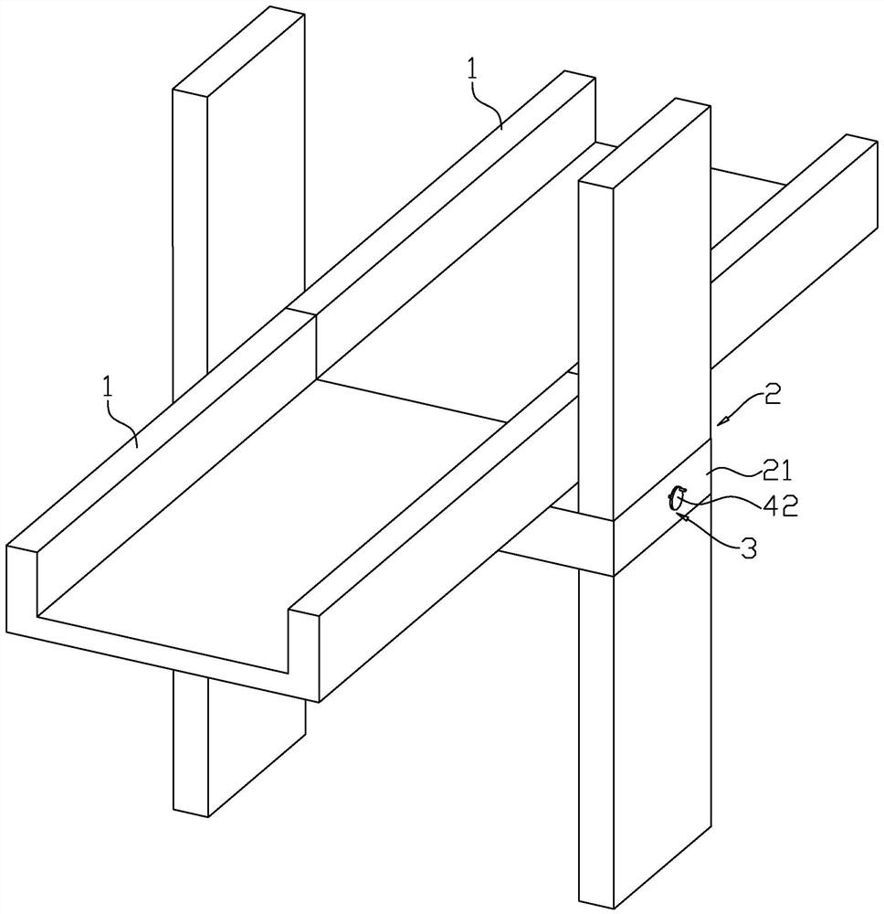
[0037] The embodiment of the present application discloses an installation structure of a cable tray, such as figure 1 As shown, it includes a plurality of bridge bodies 1, and a mounting frame 2 is installed between two adjacent bridge bodies 1. The two ends of the mounting frame 2 are respectively fixed to the ground and the top of the wall through expansion bolts, and the mounting frame 2 includes a horizontal plate 21 .

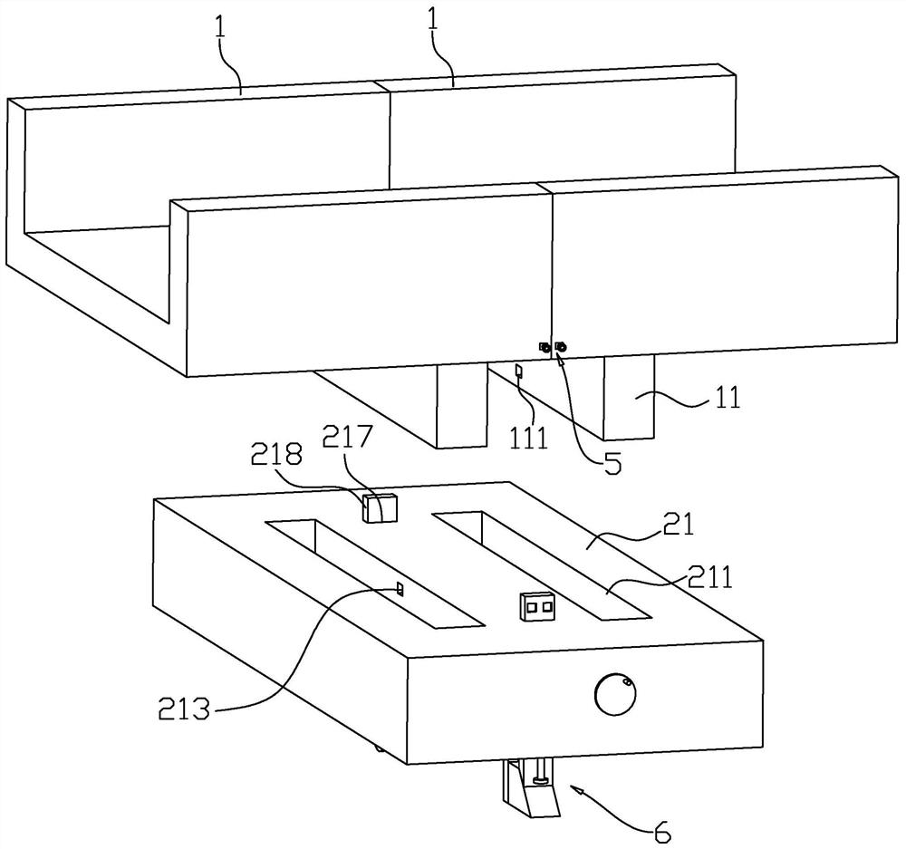
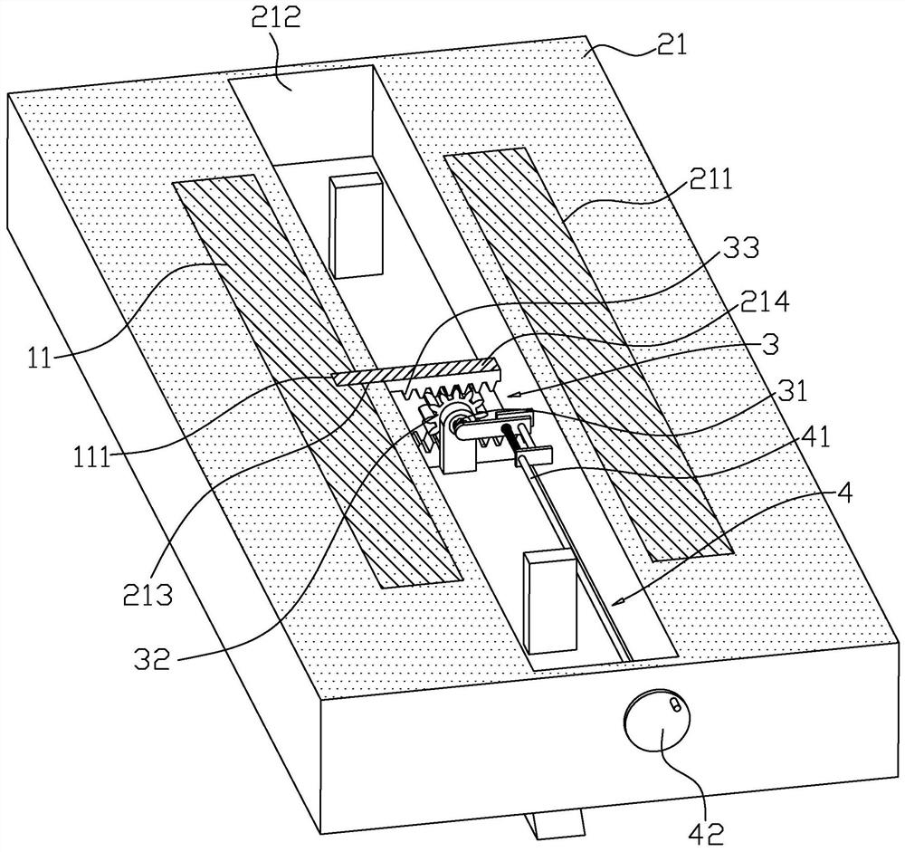
[0038] like figure 2 and image 3 As shown, the bottoms of the opposite ends of the adjacent two bridge bodies 1 are respectively fixed with first insert blocks 11, and the top of the horizontal plate 21 is provided with two first slots 211, and the two first insert blocks 11 are respectively inserted into Two first slots 211; an inner cavity 212 is opened in the horizontal plate 21, first through holes 213 are respectively opened on both sides of the...


PUM


Abstract

The invention relates to an installation structure of a cable bridge. The installation structure comprises a plurality of bridge bodies. A mounting frame is mounted between every two adjacent bridge bodies. The two ends of the mounting frame are fixedly connected to the ground and a wall top respectively. The mounting frame comprises a horizontal plate, first inserting blocks are fixedly connectedto the bottoms of the opposite ends of every two adjacent bridge bodies respectively, two first inserting grooves are formed in the top of the horizontal plate, and the two first inserting blocks areinserted into the two first inserting grooves respectively. An inner cavity is formed in the horizontal plate, first through holes are formed in the two sides of the inner cavity correspondingly, first limiting blocks are slidably connected into the two first through holes correspondingly, first limiting grooves are formed in the opposite inner sides of the two first inserting blocks correspondingly, and the two first limiting blocks are inserted into the two first limiting grooves correspondingly. A driving device for driving the two first limiting blocks to move back to back or face to faceis mounted in the inner cavity. According to the invention, the possibility of shaking of the cable bridge can be reduced.

Description

technical field [0001] The present application relates to the technical field of cable laying, and in particular, to an installation structure of a cable tray. Background technique [0002] Currently, cable laying refers to the process of laying and installing cables along a surveyed route to form a cable route. According to the occasion of use, it can be divided into several laying methods such as overhead, underground (pipeline and direct burial), underwater, wall and tunnel. Reasonable selection of cable laying method is very important to ensure the transmission quality, reliability and construction maintenance of the line. The distribution cables in the city can be laid in the overhead and on the wall. [0003] For related technology, reference may be made to the Chinese utility model patent with the authorized publication number CN204441814U, which discloses a cable tray and a tray assembly using the cable tray. The cable tray includes a left side plate and a right si...

Claims


Application Information

Patent Timeline
Patent Type & Authority Applications(China)
IPC IPC(8): H02G3/04
CPCH02G3/0456
Inventor 苏养龙陈长虹王佳玉王磊磊
Owner BEIJING EAST GRAND CONSTR GRP
Why Eureka
Try Eureka