a winding mechanism

A technology of winding mechanism and winding rod, which is applied in the manufacture of electrical components, circuits, cables/conductors, etc., can solve the problems of low efficiency and high cost of "8"-shaped wires, and achieve labor cost savings, work efficiency improvement, and movement smooth and effective effect

Active Publication Date: 2022-02-11
NANJING COLLEGE OF INFORMATION TECH
View PDF0 Cites 0 Cited by
  • Summary
  • Abstract
  • Description
  • Claims
  • Application Information

AI Technical Summary

Problems solved by technology

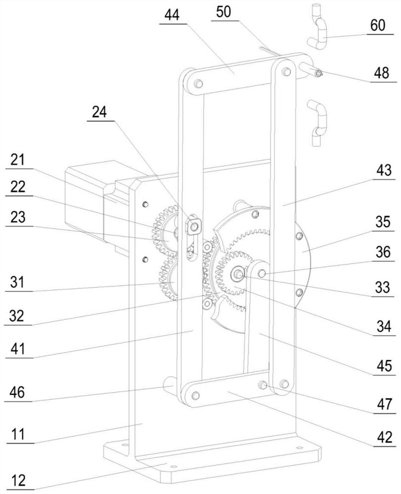
[0003] The purpose of the present invention is to provide a winding mechanism to solve the problems of low efficiency and high cost of manual winding "8" shaped wire handles in the prior art

Method used


Image

  • a winding mechanism
  • a winding mechanism

Examples


Embodiment Construction

[0027] In order to make the technical means, creative features, goals and effects achieved by the present invention easy to understand, the present invention will be further described below in conjunction with specific embodiments.

[0028] It should be noted that, in the description of the present invention, the terms "front", "rear", "left", "right", "upper", "lower", "inner", "outer" and the like indicate orientations or positions The relationship is based on the orientation or positional relationship shown in the drawings, and is only for the convenience of describing the present invention and does not require that the present invention must be constructed and operated in a specific orientation, and thus should not be construed as a limitation of the present invention. The terms "front", "rear", "left", "right", "upper" and "lower" used in the description of the present invention refer to the directions in the drawings, and the terms "inner" and "outer" refer to is the dir...


PUM


Abstract

The invention discloses a winding mechanism, which comprises a frame and a winding rod. The frame is provided with a hinge support. The winding rod includes a long swing rod, a short swing rod, a connecting rod and a winding rod. Both the first end of the rod and the first end of the short swing rod are connected with the hinge support, the second end of the long swing rod is connected with the first end of the winding rod, and the second end of the winding rod is connected with a lead pipe , the second end of the short swing link is connected with the first end of the connecting rod, and the second end of the connecting rod is connected with the winding rod; the frame is connected with the first transmission device, the second transmission device and the drive device, and the drive The output end of the device is connected with the first transmission device, and the driving device works through the first transmission device and the second transmission device to drive the lead tube on the winding rod to do "8" movement; , to achieve automatic winding, improve work efficiency and save labor costs.

Description

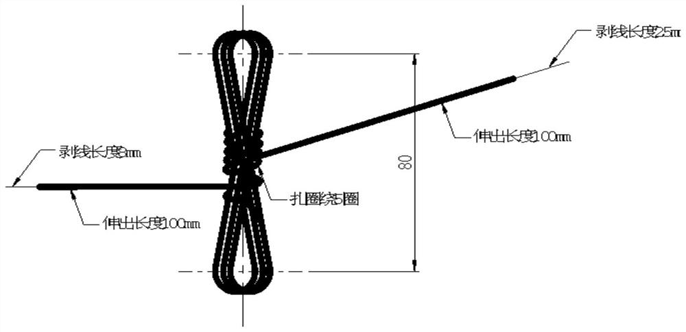
technical field [0001] The invention relates to the technical field of electric detonation guide wire production, in particular to a winding mechanism. Background technique [0002] Because the "O" type guide wire used for electric detonation has the disadvantage of being easy to be entangled, the "8" type guide wire to prevent winding came into being (see attached figure 2 ). For example, hand-winding the "8"-shaped guide wire handle is low in efficiency and high in cost, and it is difficult to meet market demand. The design of this type of automatic equipment is still in the experimental stage, and there is no relatively mature winding machine for automatically winding "8"-shaped guide wire handles. How to design a "8"-shaped winding mechanism for automatic winding of the "8"-shaped guide wire handle is a problem that we need to solve. Contents of the invention [0003] The purpose of the present invention is to provide a winding mechanism to solve the problems of low...

Claims


Application Information

Patent Timeline
Patent Type & Authority Patents(China)
IPC IPC(8): H01B13/00
CPCH01B13/0036
Inventor 潘红恩许诺陈菁岚曹宸利靳雷
Owner NANJING COLLEGE OF INFORMATION TECH
Why Eureka
Try Eureka