
An impactor gas distribution device and a matching impactor

A technology of impactor and gas distribution, which is applied to the driving device for drilling in the borehole, earthwork drilling and production, drilling equipment, etc., which can solve the problems of high cost of reserve impactor, insufficient impact energy, and large waste of impact energy, etc., to achieve The effect of simple structure

Active Publication Date: 2022-02-08
长沙天和钻具机械有限公司
View PDF6 Cites 0 Cited by
  • Summary
  • Abstract
  • Description
  • Claims
  • Application Information

AI Technical Summary

Problems solved by technology

[0002] The drilling operation of the down-the-hole drilling system is an efficient and high-quality hole-forming operation technology commonly used in the surface drilling and blasting, water well, geothermal and deep well drilling industries. However, the conventional drilling tools used in the down-the-hole drilling system often have to face The depth, cover layer thickness, and rock hardness are different in the working environment, and the performance parameters required by different working environments are different. Therefore, when using an impactor to deal with it, when the hole is not deep or the rock is not hard The waste of impact energy is large; when the hole is deep and the rock is hard, the gas volume is insufficient and the impact energy is not enough
The currently implemented measures are to store impactors with different air consumption and different impact energy to deal with this situation. Although this solution can rarely meet the requirements of the construction method, the cost of the required reserve impactors is too high, especially in the face of different construction site, and it is more obvious when the distance is far

Method used


Image

  • An impactor gas distribution device and a matching impactor
  • An impactor gas distribution device and a matching impactor
  • An impactor gas distribution device and a matching impactor

Examples


Embodiment 1

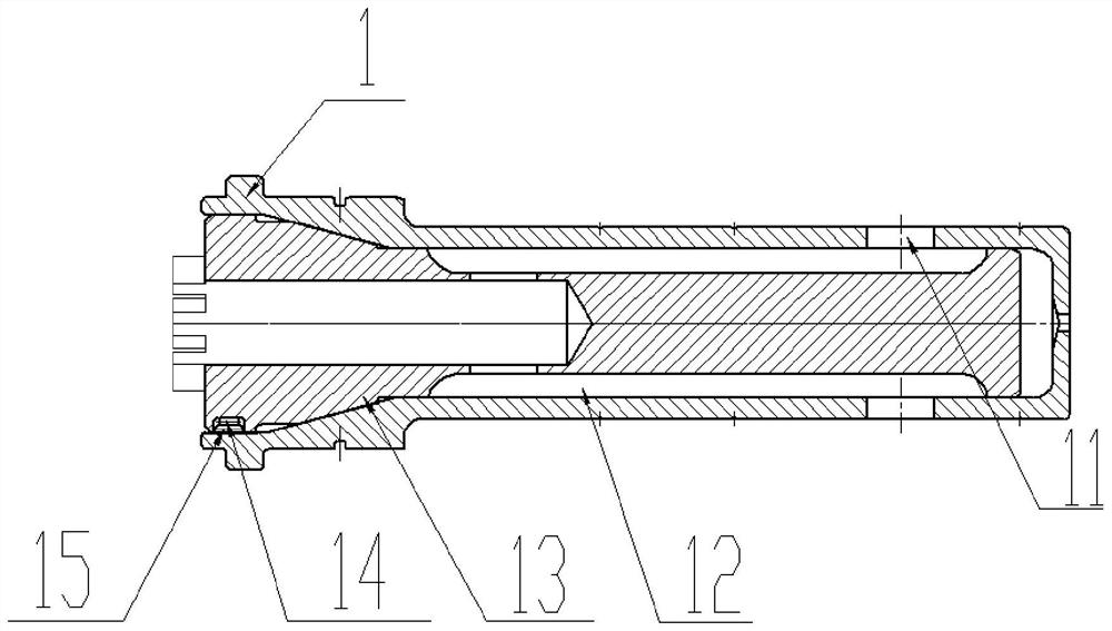
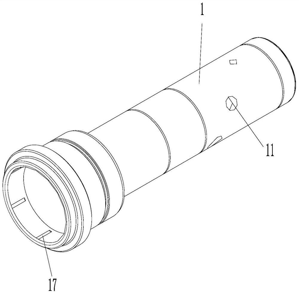
[0025] like figure 2 , 3 4, another impactor gas supply device, including a gas rod 1 mounted within the impactor, and a cavity that matches the size of the distribution roller core 13 in the middle of the housing rod 1. The gas bar core 13 is mounted in the cavity of the gas bar 1, and the central portion of the gas bar core 13 is provided with an intake passage along the axial direction, and the outer wall of the belt roller core 13 is provided with a plurality of sets of travel axes. To the arrangement gas groove group, each set of gas groove group includes two gas grooves 12, the gas groove 12, is assigned centrally, and the gas tank is centrally symmetrical. A gas groove 12 is formed between the air channel and the inner wall of the gasket 1, and the flow area of ​​the gas trails of different groups is different, and the gas groove 12 communicates with the intake passage, the gas The rod 1 is provided with a gas hole 11 for communicating with the antergeral chamber and the re...

Embodiment 2

[0030] Example 2: As an application of the impactor gas discharge device of the device:

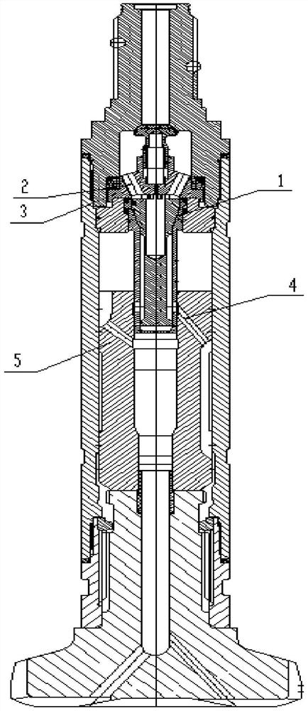
[0031] like figure 1 As shown, an impactor includes an impactor gas distribution device in Example 1. The impactor gas distribution device is mounted between the impact valve seat 3 and the piston 5, the A card assembly is provided in the outside of the impactor gas supply device. The impactor outer cylinder is provided with a plurality of card slots that are supported in the card, and the impactor gas distribution device passes the circumference of the card. In the outer cylinder, and by mounting the impactor joint mounted on the hob artone joint in the outer cylinder, the counter-stop valve 2 is in communication with the gas trails through the alloy roller core 13, said The gas supply rod 1 is inserted into the intake passage of the piston 5.

[0032] The specific impactor uses the configuration process as follows:

[0033]First, according to the geological environment using the site, such ...

Embodiment 3

[0035] The application of specific examples is as follows:

[0036] A three sets of gas hole, the position of the first set of gas holes, such that the position of the piston is 73 mm, the position of the second set of gas hole, so that the maximum stroke of the piston is 82mm, the third set of gas The position of the pond makes the maximum stroke of the piston of 94mm.

[0037] A three sets of gas trails are provided on the allocation roller core 13, and the first set of airway flow is 480mm. 2 The flow area of ​​the second set of airway is 1050 mm. 2 , The third set of airway diameter flow area is 1780mm 2 .

[0038] In this embodiment, the pore demand: 230 ~ 240mm, the amount of water reaches 20m 3 / min.

[0039] Designed a hole process: It is expected to be 180 meters deep, the actual hole is deep: 20 meters after excessive water. The first stage: the cover is cooked, and the high frequency, the small impact work is drilled into the rock. The second stage: After stabilizing t...


PUM


Abstract

A gas distribution device for an impactor and a matching impactor, including a gas distribution rod, the gas distribution rod is provided with a gas distribution rod core to connect the air inlet channel of the impactor to the air chamber passage at the rear of the impactor, and the gas distribution rod The core is provided with air intake passages of different cross sections and rotatable adjustment positions, and the air distribution rod has air holes of different flow areas, angles and positions. A rotary locking round key is provided between the gas distribution rod and the gas distribution rod core. According to different construction hole depths and rock hardness conditions, the relative position of the air distribution rod core and the air distribution rod can be rotated to connect different air intake channels, so as to change the air consumption, change the piston stroke, and thus change the impact energy of the piston and the frequency of the impactor. Purpose. The structure of the device is simple, and the impactor can be adjusted according to changes in the external environment such as hole depth and rock hardness, and the performance parameters of the impactor can be changed to meet the needs of different hole depths and different use environments.

Description

Technical field [0001] The present invention relates to an impactor gas supply device and a supporting impactor. Background technique [0002] The drilling operation of the sub-hole drill system is currently the high-efficiency high-quality complex operation technology used in the open-air drilling blasting, well, geothermal and deep well drilling industry. Deep, covering layer thickness, rock hardness different work environments, while different operating environments have different performance parameters, and thus when using an impactor, when the holes are not deep or the amount of rock is not hard. The impact of the impact has a lot of money; when the hole is deep, the amount of gas is inadequate when the rock is hard, and the impact work is not enough. The current implementation is that the reserve of different air consumables, the impact of different impact works should respond, although this program will meet the requirements of the work, but the cost of the reserve impact ...

Claims


Application Information

Patent Timeline
Patent Type & Authority Patents(China)
IPC IPC(8): E21B4/14
CPCE21B4/14
Inventor 师明辉李亮吉伟
Owner 长沙天和钻具机械有限公司
Learn More