
Electrolytic cleaning device

A technology of electrolytic cleaning and electrolysis of water, applied in the direction of electrolytic components, electrolytic process, etc., can solve the problems of difficult to realize automatic production, rely on the use of electrolytic cleaning agent, etc., and achieve the effect of saving manpower and high degree of automation

Inactive Publication Date: 2020-11-13
CITIC DICASTAL
View PDF5 Cites 0 Cited by
  • Summary
  • Abstract
  • Description
  • Claims
  • Application Information

AI Technical Summary

Problems solved by technology

[0003] However, the above cleaning method is only suitable for batch production, it is difficult to realize automatic production, and it needs to rely on the use of electrolytic cleaning agent

Method used


Image

  • Electrolytic cleaning device
  • Electrolytic cleaning device
  • Electrolytic cleaning device

Examples


Embodiment Construction

[0027] It should be noted that, in the case of no conflict, the embodiments of the present invention and the features in the embodiments can be combined with each other.

[0028] The technical solutions of the present invention will be clearly and completely described below with reference to the accompanying drawings and in conjunction with the embodiments. Apparently, the described embodiments are only some, not all, embodiments of the present invention. Based on the embodiments of the present invention, all other embodiments obtained by persons of ordinary skill in the art without making creative efforts belong to the protection scope of the present invention.

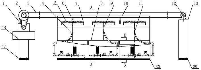
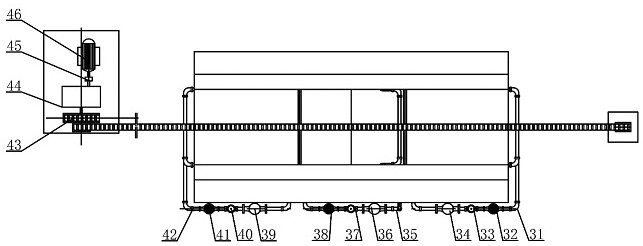
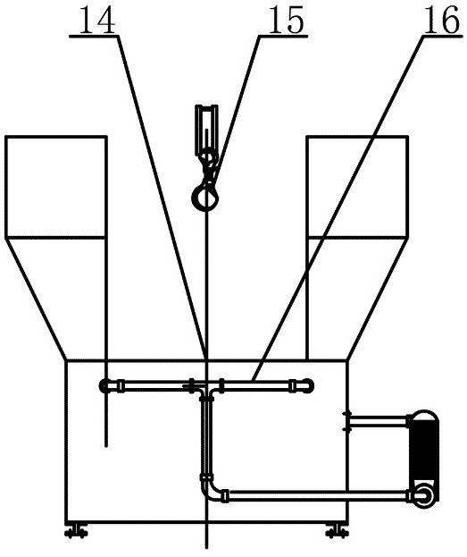
[0029] Refer below Figure 1 to Figure 6 The electrolytic cleaning device of the embodiment of the present invention will be described in conjunction with the embodiments.

[0030] An electrolytic cleaning device comprising a transport system capable of transporting metal workpieces; an electrolysis system capable o...


PUM


Abstract

The invention discloses an electrolytic cleaning device which comprises a conveying system that can convey metal workpieces; an electrolysis system that can electrolyze water to form hydrogen ions andhydroxyl ions, wherein acidic water is formed near a cathode electrode plate, and alkaline water is formed near an anode electrode plate; and a spraying system that comprises an alkaline water spraying component, wherein the alkaline water spraying component can spray alkaline water to the surfaces of the workpieces. No cleaning agent needs to be added in the cleaning process, and environmental protection and saving are achieved. And the automation degree is high, cleaning of the workpieces can be automatically completed, and manpower is saved.

Description

technical field [0001] The invention relates to the technical field of industrial cleaning, in particular to an electrolytic cleaning device. Background technique [0002] Electrolytic cleaning is a common method of cleaning metal parts. In the traditional electrolytic cleaning technology, the metal parts to be cleaned are hung on the cathode or anode and placed in the electrolyte. When direct current is applied, the interfacial tension between the metal and the electrolyte solution is reduced due to polarization, and the solution penetrates into the electrolyte. Under the dirt on the surface of the workpiece, the interface plays an oxidation or reduction role, and produces a large number of air bubbles. When the air bubbles gather to form an airflow that escapes from the gap between the dirt and the metal, it acts as agitation and stirring to make the dirt flow from the surface of the workpiece. The surface falls off, achieving the purpose of removing dirt and cleaning the...

Claims


Application Information

Patent Timeline
Patent Type & Authority Applications(China)
IPC IPC(8): C25F7/00C25F1/02
CPCC25F7/00C25F1/02
Inventor 赵磊熊国源杨小禹马超张立伟王博程娇
Owner CITIC DICASTAL
Learn More