
A feeding mechanism for electrical automation equipment

A technology of electrical automation and feeding mechanism, applied in the direction of conveyors, conveyor objects, transportation and packaging, etc., can solve the problems of increasing the use cost of feeding mechanisms, shortening the service life of conveyor belts, and inconvenient rapid material transportation, etc., to improve practicability, The effect of increasing the scope of application and facilitating rapid delivery

Active Publication Date: 2021-04-09
江苏扬林电气有限公司
View PDF14 Cites 0 Cited by
  • Summary
  • Abstract
  • Description
  • Claims
  • Application Information

AI Technical Summary

Problems solved by technology

[0004] The purpose of the present invention is to provide a feeding mechanism for electrical automation equipment, to solve the problems in the above background technology that the material cannot be guided and corrected, resulting in material falling, which is inconvenient for the rapid transportation of the material; and the conveyor belt on the feeding mechanism cannot be corrected. Cleaning will cause dust to accumulate on the conveyor belt, which shortens the service life of the conveyor belt and increases the cost of the feeding mechanism

Method used


Image

  • A feeding mechanism for electrical automation equipment
  • A feeding mechanism for electrical automation equipment
  • A feeding mechanism for electrical automation equipment

Examples


Embodiment Construction

[0041] The following will clearly and completely describe the technical solutions in the embodiments of the present invention with reference to the accompanying drawings in the embodiments of the present invention. Obviously, the described embodiments are only some, not all, embodiments of the present invention. Based on the embodiments of the present invention, all other embodiments obtained by persons of ordinary skill in the art without making creative efforts belong to the protection scope of the present invention.

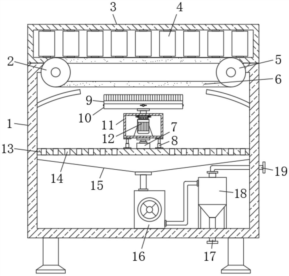
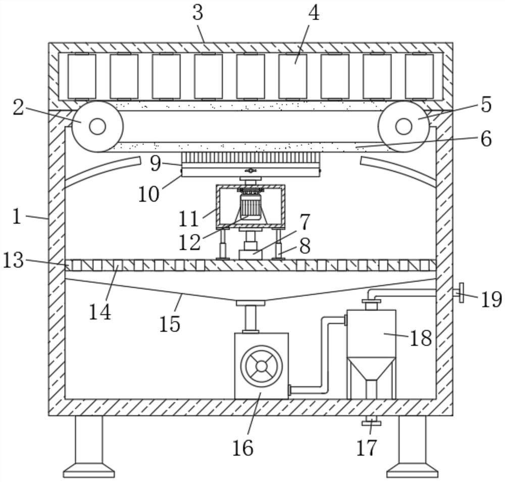
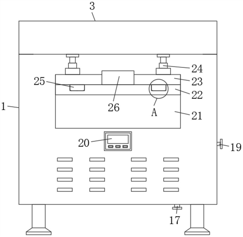
[0042] see Figure 1-Figure 10 As shown, the present invention provides a technical solution: a feeding mechanism for electrical automation equipment, including a frame 1, a symmetrically distributed driven roller 2 and a driving roller 5 are movably installed on the top of the frame 1, and the frame 1 One side of the drive roller 5 is fixed with a second motor 28 that is rotatably connected to the drive roller 5, a conveyor belt 6 is connected between the dri...


PUM


Abstract

The invention discloses a feeding mechanism for electrical automation equipment, and relates to the technical field of feeding mechanisms. The feeding mechanism for electrical automation equipment includes a frame, and symmetrically distributed driven rollers and driving rollers are movably installed on the top inside the frame. , and one side of the frame is fixed with a second motor that is rotatably connected to the driving roller, a conveyor belt is connected between the driven roller and the driving roller, a controller is installed on the front surface of the frame, and the top of the frame is along the Both sides of the symmetric feeding direction are equipped with guiding and correcting mechanisms. The guiding and correcting mechanism includes a guiding device and a position adjustment mechanism. Through the setting of the guiding and correcting mechanism in the present invention, the material can be guided and corrected during the feeding process, effectively preventing It can avoid material deviation, so as to facilitate the rapid conveying of materials, and greatly improve the feeding efficiency; and it can avoid material falling and damage, and can ensure the normal use of materials, so as to realize high-quality and efficient conveying of materials.

Description

technical field [0001] The invention belongs to the technical field of feeding mechanisms, and in particular relates to a feeding mechanism for electrical automation equipment. Background technique [0002] The use of automation technology in electrical automation equipment can not only liberate people from heavy physical labor, some mental work, and harsh and dangerous working environments, but also expand human organ functions, greatly improve labor productivity, and enhance human understanding of the world and transformation. The world's capabilities are widely used in industry, agriculture, military, scientific research, transportation, commerce, medical care, services and households. When the electrical automation equipment processes the materials, it is often necessary to transport the materials through the feeding mechanism to realize automatic feeding and facilitate the automatic processing of the materials. [0003] However, the feeding mechanism for electrical aut...

Claims


Application Information

Patent Timeline
Patent Type & Authority Patents(China)
IPC IPC(8): B65G47/22B65G45/18B65G15/30B65G45/26
CPCB65G15/30B65G45/18B65G45/26B65G47/22
Inventor 章小燕
Owner 江苏扬林电气有限公司
Learn More