
A pressure-adjustable midwifery device

A midwifery device and adjustable pressure technology, applied in obstetrics and gynecology equipment, etc., can solve problems such as fetal injury, suction head and fetal scalp loss, fetal head injury, etc.

Active Publication Date: 2021-07-02
安晓娜
View PDF5 Cites 0 Cited by
  • Summary
  • Abstract
  • Description
  • Claims
  • Application Information

AI Technical Summary

Problems solved by technology

Among them, the electric negative pressure suction machine has a complex structure and high cost, and because it needs to be equipped with a power supply, it is not suitable for mobile medical equipment.
However, the manual air extraction device cannot accurately control the negative pressure value of the suction head
In addition, for the manual suction device, if the vacuum is too high, it will easily cause harm to the fetus. During the midwifery process, due to the action of the fetal hair, there will be tiny gaps between the suction head and the fetal scalp. The effect will cause air or amniotic fluid to enter the suction head, thereby reducing the negative pressure in the suction head and causing the suction head and the fetal scalp to fall off. It is necessary to re-attract the suction head to the fetal head, and it is easy to operate for many times fetal head injury

Method used


Image

  • A pressure-adjustable midwifery device
  • A pressure-adjustable midwifery device
  • A pressure-adjustable midwifery device

Examples


Embodiment 1

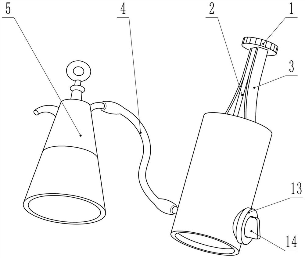
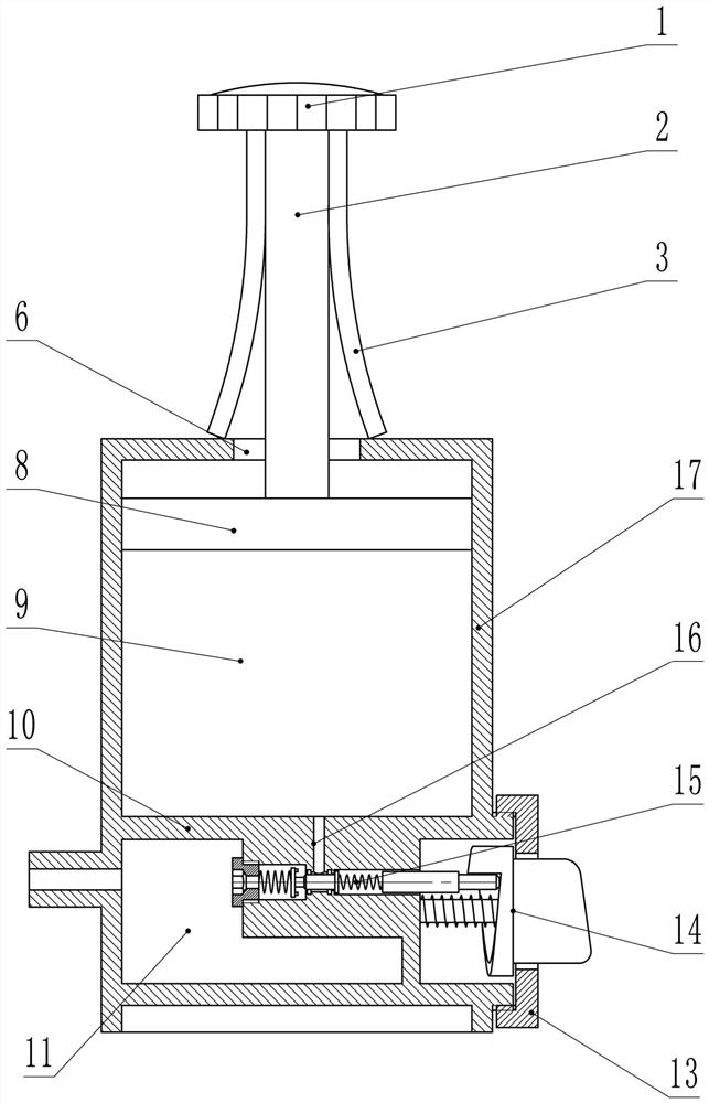
[0017] In embodiment 1, such as figure 1 As shown, the present invention includes a suction device 5, a conduit 4 and a negative pressure device. Both ends of the conduit 4 are respectively connected to the suction device 5 and the negative pressure device, so that the air between the suction device 5 and the negative pressure device is communicated.

[0018] Such as figure 2 , 4 As shown, the negative pressure device includes a cylindrical tank body 17 in which a partition 10 and a piston 8 are arranged. The partition 10 is fixed in the middle of the tank body 17 , and divides the inside of the tank body 17 into upper and lower cavities, namely an upper cavity 9 and a lower cavity 11 . The catheter 4 is connected to the lower cavity. The piston 8 is located in the upper cavity 9, the periphery of the piston 8 is airtightly connected to the inner surface of the tank body 17, the upper surface of the piston 8 is fixedly connected to the piston rod 2, and the upper wall of ...

Embodiment 2

[0028] In embodiment 2, such as Figure 5 , 6 As shown, in addition to the technical features in Embodiment 1, this embodiment also includes an intake valve 12 . For ease of description, it is set in the intake valve 12, the end close to the knob 14 is the outer end, and the opposite direction is the inner end.

[0029] The inlet valve 12 is located in the tank lower cavity 11 close to the outlet valve 15 . The intake valve 12 communicates with the outside of the lower chamber 11 and the tank body 17, and its function is to allow external air to enter the lower chamber 11 to increase the air pressure in the lower chamber 11.

[0030] Such as Image 6 As shown, the intake valve 12 includes a No. 1 hole 21 , a No. 1 spring 20 , a No. 2 spring 24 , a No. 1 cylinder 22 and a No. 2 cylinder 25 . The No. 1 hole 21 is a horizontal stepped hole with a thick inside and a thin outer side. A No. 1 bolt 19 is provided at the inner side of the No. 1 hole 21, and a shaft center hole is ...


PUM


Abstract

The invention discloses a pressure-adjustable midwifery device, which belongs to the field of medical equipment, and is characterized in that it includes a suction device, a catheter and a negative pressure device; the two ends of the catheter are respectively connected to the suction device and the negative pressure device. On the device, the air between the suction device and the negative pressure device is connected; the negative pressure device includes a cylindrical tank, and a partition and a piston are arranged in the tank; the partition is fixed on the tank body In the middle position, the inner part of the tank is divided into upper and lower chambers, namely an upper chamber and a lower chamber; the conduit is connected to the lower chamber; the piston is located in the upper chamber, and the periphery of the piston is airtightly connected with the inner surface of the tank. The upper surface of the piston is fixedly connected to the piston rod; an air outlet valve is arranged in the lower chamber of the tank body, and the air outlet valve communicates with the lower chamber and the upper chamber. Compared with the prior art, it has the characteristics of adjustable and constant negative pressure.

Description

technical field [0001] The present invention is a divisional application of the invention patent "A Portable Midwifery Device" (Application No.: 2018101104491), which relates to a medical device, especially a portable midwifery device suitable for puerpera. Background technique [0002] At present, when the obstetrics fails to deliver newborns to the puerpera, medical staff often need to use midwifery devices to help the fetus deliver. The midwifery devices include a suction device and a negative pressure device. Negative pressure, the fetal head is pulled by the negative pressure of the suction head, thereby assisting the delivery of the fetus. In actual use, different negative pressure values ​​should be selected according to the actual situation of the mother and the fetus. For example, if the fetal head position is low, 40kpa negative pressure can be used; if the fetal head position is high or the fetus is large, 60kpa negative pressure can be used for those with difficu...

Claims


Application Information

Patent Timeline
Patent Type & Authority Patents(China)
IPC IPC(8): A61B17/44
CPCA61B17/442
Inventor 安晓娜苗海龙赵子成宋艳周绪
Owner 安晓娜
Learn More