Novel energy-saving and efficient universal heat dissipation device for electromechanical equipment

A technology of electromechanical equipment and heat dissipation device, which is applied in the construction parts of electrical equipment, cooling/ventilation/heating transformation, electrical components, etc., can solve the problems of low heat dissipation efficiency of electromechanical equipment, achieve the effect of improving heat dissipation efficiency and reducing dust adhesion

Inactive Publication Date: 2020-11-10
贵州博睿联合科技有限公司
View PDF0 Cites 0 Cited by
  • Summary
  • Abstract
  • Description
  • Claims
  • Application Information

AI Technical Summary

Problems solved by technology

[0003] The invention provides a new type of energy-saving and high-efficiency general heat dissipation device for electromechanical equipment, the purpose of which is to solve the problem of low heat dissipation efficiency of electromechanical equipment

Method used


Image

  • Novel energy-saving and efficient universal heat dissipation device for electromechanical equipment
  • Novel energy-saving and efficient universal heat dissipation device for electromechanical equipment
  • Novel energy-saving and efficient universal heat dissipation device for electromechanical equipment

Examples


no. 1 example

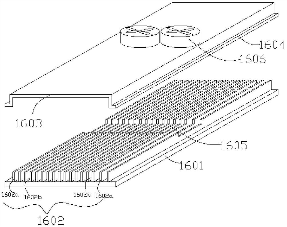
[0032] Such as image 3 As shown, the top heat dissipation mechanism 16 includes a top plate 1601 constituting the top of the electromechanical equipment housing 1. The upper end of the top plate 1601 is provided with a heat sink group 1602 composed of a plurality of heat sinks 1602a arranged side by side. The middle part of the heat sink group 1602 is concave, and the heat sink group 1602 is provided with a door-shaped cover body 1603 that is pressed against the upper ends of a plurality of heat sinks 1602a, and the two ends of the airflow channel 1602b between adjacent heat sink fins 1602a of the heat sink group 1602 are kept unobstructed, and both sides of the door-shaped cover body 1603 are There is an edge 1604 bolted to the top plate 1601, and an airflow chamber 1605 is formed between the door-shaped cover body 1603 and the depression in the middle of the heat sink group 1602, and the airflow chamber 1605 communicates with the airflow channel 1602b between adjacent heat s...

no. 2 example

[0034] Such as Figure 4 As shown, the top heat dissipation mechanism 16 includes a top plate 1601 constituting the top of the electromechanical equipment housing 1. The upper end of the top plate 1601 is provided with a heat sink group 1602 composed of a plurality of heat sinks 1602a arranged side by side. The door-shaped cover body 1603 at the upper end of the plurality of heat sinks 1602a, and the two ends of the airflow channel 1602b between adjacent heat sink fins 1602a of the heat sink group 1602 are kept unobstructed, and both sides of the door-shaped cover body 1603 are provided with bolts connected to the top plate 1601 The edge 1604 of the door-shaped cover 1603 is provided with an airflow chamber 1605 communicating with the airflow channel 1602b between adjacent heat sinks 1602a of the heat sink group 1602, and two sets of impeller fans 1606 are arranged inside the airflow chamber 1605.

[0035] Such as Figure 5 As shown, in this embodiment, the filter layer 9 inc...


PUM


Abstract

The invention discloses a novel energy-saving high-efficiency electromechanical equipment universal heat dissipation device, and the device comprises an electromechanical equipment shell, a cooling medium box for supporting the body of the electromechanical equipment shell is arranged at the bottom of the electromechanical equipment shell, the interior of the cooling medium box is divided into anupper layer and a lower layer through a horizontal partition plate, a water cooling chamber is arranged on the lower layer in the cooling medium box, and a dust falling chamber is arranged on the upper layer in the cooling medium box. A water pump is arranged in the water cooling chamber and communicated with a hollow copper pipe coiled on the inner side wall of the electromechanical equipment shell through a pipeline, an air blower is arranged outside the electromechanical equipment shell, an air outlet of the air blower is communicated with the interior of the dust falling chamber, and T-shaped airflow channels are formed in the vertical side walls of the periphery of the electromechanical equipment shell side by side. An air flow opening in the lower end of the T-shaped air flow channelcommunicates with a cavity above the filtering layer in the dust falling chamber, and a top heat dissipation mechanism is arranged at the top of the electromechanical equipment shell. Multi-stage cooling of the electromechanical equipment can be achieved, and the heat dissipation effect is obvious.

Description

technical field [0001] The invention relates to the technical field of electromechanical equipment, in particular to a novel energy-saving and high-efficiency universal cooling device for electromechanical equipment. Background technique [0002] When the electromechanical equipment is working, since a large amount of heat is generated, it is necessary to dissipate heat by means of a heat sink. However, the existing heat dissipation devices for electromechanical equipment mainly use cooling fans to suck and dissipate heat from the interior of the electromechanical equipment, but only in the initial stage of operation of the electromechanical equipment, there is an obvious heat dissipation effect. Once the electromechanical equipment runs for a long time, the inside of the housing will The temperature will rise. At this time, only relying on the cooling fan, the cooling efficiency is low, and it cannot meet the requirements. Especially in summer, the external temperature of t...

Claims


Application Information

Patent Timeline
Patent Type & Authority Applications(China)
IPC IPC(8): H05K7/20
CPCH05K7/20181H05K7/20272H05K7/20409
Inventor 尧莎莎
Owner 贵州博睿联合科技有限公司
Why Eureka
Try Eureka