Injection molding equipment for lower shell of direct-current brushless motor and working method of injection molding equipment

A technology of brushless DC and injection molding equipment, which is applied in the direction of electromechanical devices, manufacturing motor generators, electrical components, etc., can solve the problems of low work efficiency, need for manual removal, high labor intensity, etc., and achieve the effect of high work efficiency

Active Publication Date: 2020-11-10
阜南县特立电子有限公司
View PDF3 Cites 1 Cited by
  • Summary
  • Abstract
  • Description
  • Claims
  • Application Information

AI Technical Summary

Problems solved by technology

[0003] The object of the present invention is to provide a kind of injection molding equipment and its working method for the lower casing of the DC brushless motor. In the present invention, the injection molding solution is added into the injection plastic hopper, and the injection molding solution enters the space between the upper mold and the lower mold through a conduit. In the injection molding cavity, after the injection molding solution cools down, the injection molding solution solidifies in the injection molding cavity and forms the lower casing of the motor. The upper mold is driven up by the upper mold cylinder, and the suction cup is moved by the moving cylinder, so that the suction cup moves to the top of the motor lower casing. The suction cup is driven down by the lifting cylinder so that the bottom of the suction cup is in contact with the top of the lower casing of the motor, and the lower casing of the motor is held by the suction cup. The lifting cylinder drives the lower casing of the motor to separate from the upper mold, and the moving cylinder drives the lower casing of the motor to move to the top seat and Between the bases, the suction cup loosens the motor lower casing, and puts the motor lower casing into the storage slot of the storage board. The invention can quickly take out the motor lower casing and move it to the storage board, which solves the problem of the traditional motor lower casing After the injection molding is completed, it needs to be taken out manually, which is a technical problem of high labor intensity and low work efficiency;

Method used


Image

  • Injection molding equipment for lower shell of direct-current brushless motor and working method of injection molding equipment
  • Injection molding equipment for lower shell of direct-current brushless motor and working method of injection molding equipment
  • Injection molding equipment for lower shell of direct-current brushless motor and working method of injection molding equipment

Examples


Embodiment Construction

[0032] The technical solutions of the present invention will be clearly and completely described below in conjunction with the embodiments. Apparently, the described embodiments are only some of the embodiments of the present invention, not all of them. Based on the embodiments of the present invention, all other embodiments obtained by persons of ordinary skill in the art without creative efforts fall within the protection scope of the present invention.

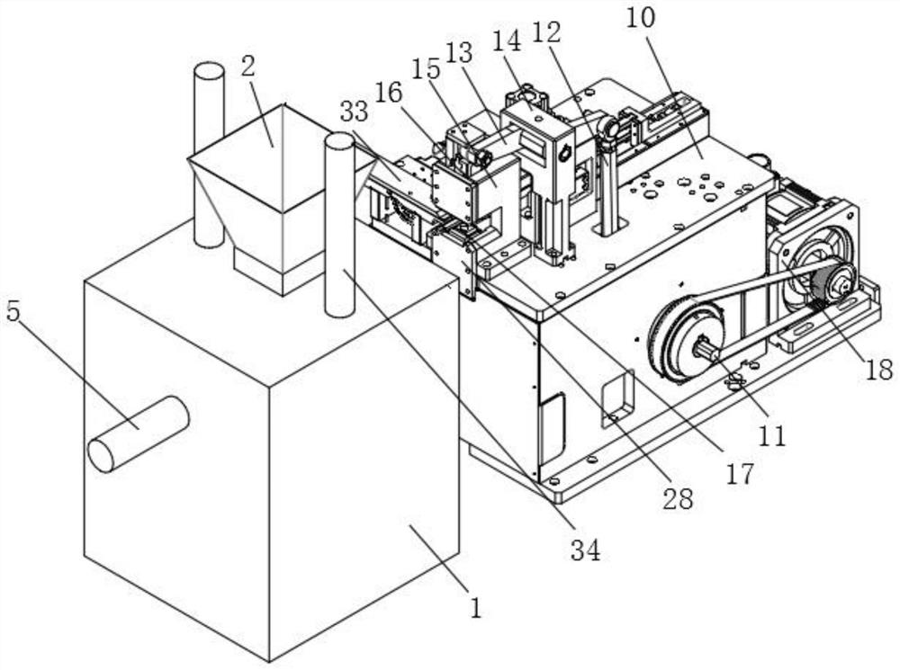
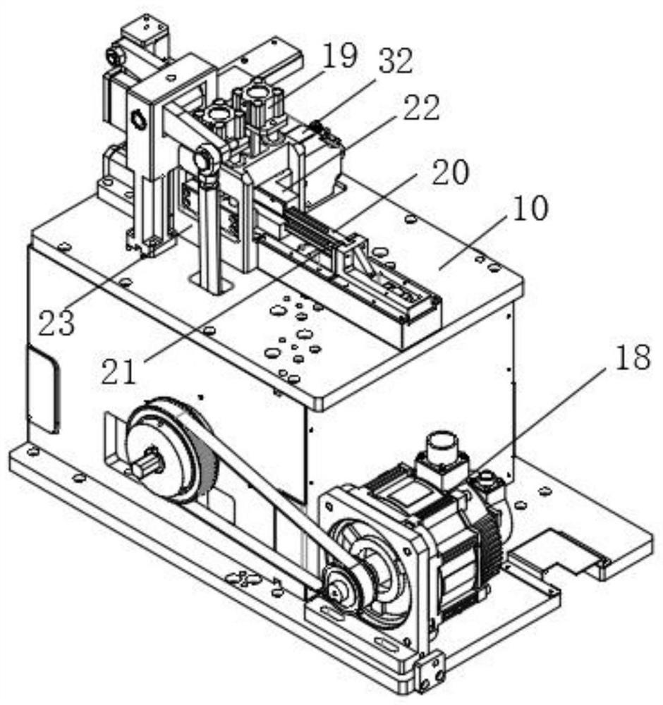
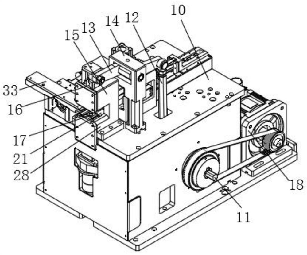
[0033] Such as Figure 1-7 As shown, an injection molding equipment for the lower casing of a DC brushless motor includes a first casing 1, a lower mold 3 is installed on the inner side of the first casing 1, and an upper mold 3 is installed above the lower mold 3. Die 4, an injection molding cavity is arranged between the upper mold 4 and the lower mold 3, an upper mold cylinder 34 is fixedly installed on the first housing 1, and the bottom end of the output rod of the upper mold cylinder 34 is fixedly connected with the u...


PUM


Abstract

The invention discloses injection molding equipment for a lower casing of a direct-current brushless motor and a working method of the injection molding equipment. The equipment comprises a first casing, a lower die and an upper die are mounted at the inner side of the first casing, an injection molding hopper is fixedly mounted at the top of the first casing, and an air cylinder mounting plate isfixedly mounted at the end of an output rod of a movable air cylinder; a lifting air cylinder is fixedly mounted on the upper surface of the air cylinder mounting plate, a suction cup is fixedly mounted at the bottom end of an output rod of the lifting air cylinder, and a base is fixedly mounted at the top of the second shell; a top seat is fixedly mounted above the base, a scraping rod is movably mounted on the top seat along the vertical direction, the bottom end of the scraping rod is connected with the top seat in a penetrating manner, and a storage plate is fixedly mounted on the upper surface of the base. According to the injection molding equipment, the lower shell of the motor can be rapidly taken out and moved to the storage plate, the working efficiency is high, the deburring effect of the lower shell of the motor is guaranteed; the outer circumferential face and the inner circumferential face of a fixing column are polished through a steel brush, and the polishing effect isgood.

Description

technical field [0001] The invention relates to the technical field of motor processing equipment, in particular to an injection molding equipment used for the lower casing of a DC brushless motor and a working method thereof. Background technique [0002] Injection molding is a method of producing industrial products. In the traditional motor lower casing, a fixed rod needs to be installed in the middle of the groove of the main body of the casing. If the welding method is adopted, the fixed rod is easy to break. In this case, the motor lower casing is in the middle of the groove. The fixed column can be formed at one time during the injection molding process, and the fixed column can be installed in the round hole of the fixed column, which can ensure the service life of the fixed column; the motor lower casing needs to be manually removed after the injection molding is completed, which is labor-intensive and low-efficiency. , The lower casing of the motor cannot be kept s...

Claims


Application Information

Patent Timeline
IPC IPC(8): H02K15/14
CPCH02K15/14
Inventor 王和平李伟德
Owner 阜南县特立电子有限公司
Why Eureka
Try Eureka