Eureka AIR delivers breakthrough ideas for toughest innovation challenges, trusted by R&D personnel around the world.

Improved 3D laser scanning imaging system

An improved technology of laser scanning imaging, which is applied in the field of laser measurement, can solve the problems of low contour accuracy and excessive scanning system volume, etc., and achieve the effect of meeting production needs

Pending Publication Date: 2020-11-10
六度人和(天津)科技有限公司
View PDF0 Cites 0 Cited by
  • Summary
  • Abstract
  • Description
  • Claims
  • Application Information

AI Technical Summary

Problems solved by technology

[0003] The technical problem to be solved by the present invention is to provide an improved 3D laser scanning imaging system, which has a simple structure and flexible movement, in view of the shortcomings of the above-mentioned 3D laser profile measurement system in the prior art, such as low profile accuracy and too large scanning system volume. , which can effectively ensure the scanning imaging accuracy and meet the production needs

Method used

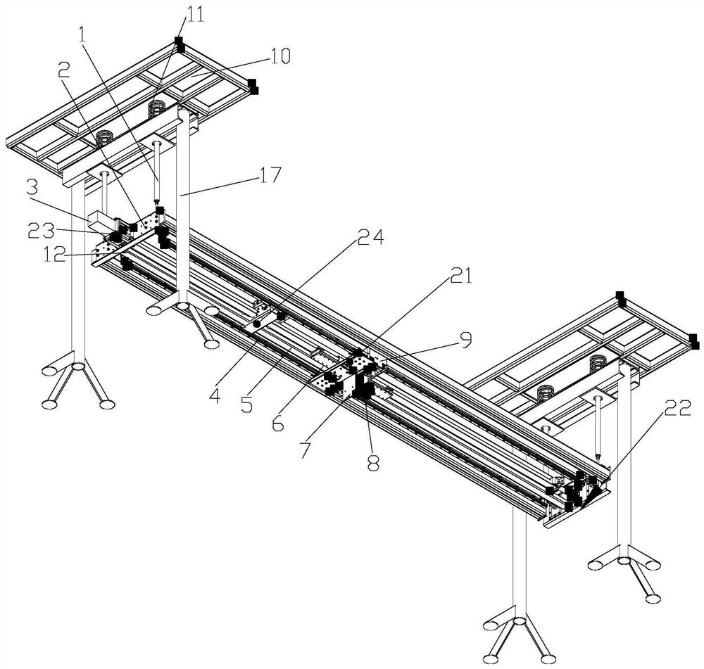
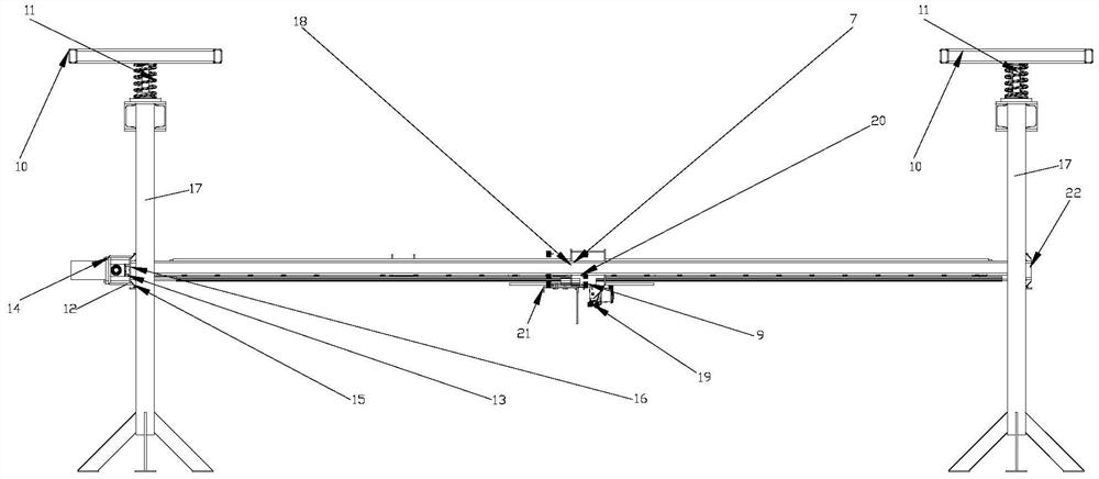
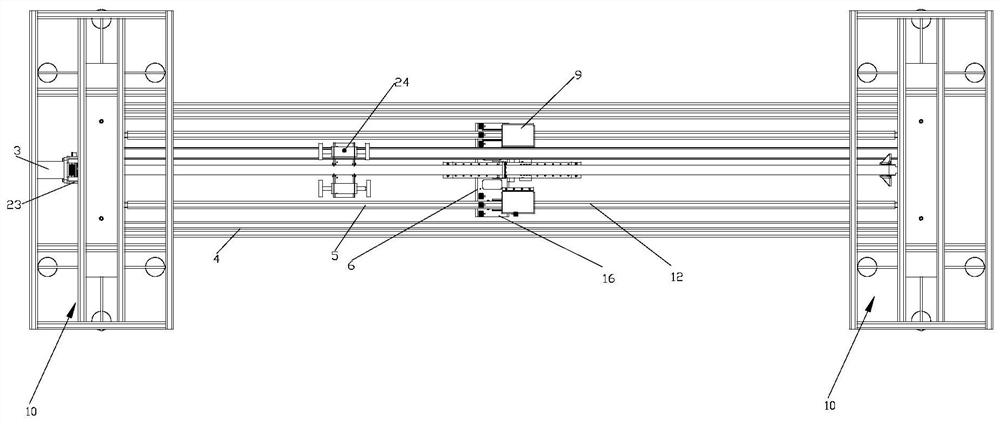

Image

  • Improved 3D laser scanning imaging system
  • Improved 3D laser scanning imaging system
  • Improved 3D laser scanning imaging system

Examples


Embodiment Construction

[0016] The specific embodiments of the present invention will be further described below in conjunction with the accompanying drawings. It should be noted here that the descriptions of these embodiments are used to help understand the present invention, but are not intended to limit the present invention. In addition, the technical features involved in the various embodiments of the present invention described below may be combined with each other as long as they do not constitute a conflict with each other.

[0017] In describing the present invention, it should be understood that the terms "center", "longitudinal", "transverse", "length", "width", "thickness", "upper", "lower", "front", " Back", "Left", "Right", "Vertical", "Horizontal", "Top", "Bottom", "Inner", "Outer", "Clockwise", "Counterclockwise", "Axial", The orientation or positional relationship indicated by "radial", "circumferential", etc. is based on the orientation or positional relationship shown in the drawi...


PUM


Abstract

The invention relates to the technical field of laser measurement, and particularly discloses an improved 3D laser scanning imaging system which comprises an outer frame and a pull rod connected withthe outer frame; a servo motor, a synchronous belt base, a linear sliding rail, a sliding block, a scanner and a scanner frame are arranged on the outer frame, and the servo motor is connected with the synchronous belt base through a synchronous belt. The sliding block is installed on the linear sliding rail, the scanner frame and the sliding block are both connected with the synchronous belt base, and the scanner is installed on the scanner frame. The improved 3D laser scanning imaging system is simple in structure and flexible in movement, can effectively guarantee the scanning imaging precision, and meets the production demands.

Description

technical field [0001] The invention relates to the technical field of laser measurement, in particular to an improved 3D laser scanning imaging system. Background technique [0002] The current 3D imaging systems are divided into: binocular 3D, grating structured light, and laser triangulation imaging; when the first two are measuring large depth of field, there will be problems with the image system defocusing after the measured object deviates from the imaging focal plane, causing measurement accuracy Significant decrease, and due to defocusing, the brightness of the light entering the individual pixel particles of the sensor is reduced, resulting in a significant reduction in the dynamic range of the system. Laser triangulation imaging converts the focal plane of a two-dimensional (x, y) image into an image containing depth information (x, z) through dimensionality reduction, thereby solving the problem of large depth of field, but due to the lack of y information in the...

Claims


Application Information

Patent Timeline
IPC IPC(8): G01B11/24
CPCG01B11/24
Inventor 白朝峰
Owner 六度人和(天津)科技有限公司
Why Eureka
Eureka Blog
Learn More