Filter ball valve

A technology for filtering ball valves and valve bodies, which is applied in the direction of filtration and separation, valve details, and valve devices. cumulative effect

Active Publication Date: 2020-11-10
NINGBO JIEKELONG PRECISION MFG
View PDF7 Cites 0 Cited by
  • Summary
  • Abstract
  • Description
  • Claims
  • Application Information

AI Technical Summary

Problems solved by technology

However, the filter in this kind of ball valve is easy to accumulate impurities in the connection between the valve core and the valve body, and the filter in it cannot be taken out for cleaning or replacement, and the accumulated impurities are easy to block the pipeline. The cylindrical filter at the bottom is not filtered The function is only to collect impurities, and the height of the cylindrical filter is relatively short compared to the overall height of the valve body. In the state of unstable water flow, it is easy to cause impurities, pollutants, etc. to flow back, and the collection of impurities is not complete.

Method used


Image

  • Filter ball valve
  • Filter ball valve
  • Filter ball valve

Examples


Embodiment approach

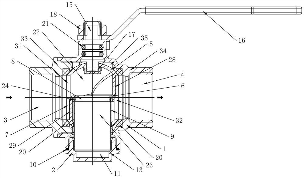
[0056] In further embodiments of the present invention, please continue to refer to Figure 1 to Figure 4 As shown, the filter screen 9 is set in a sleeve shape.

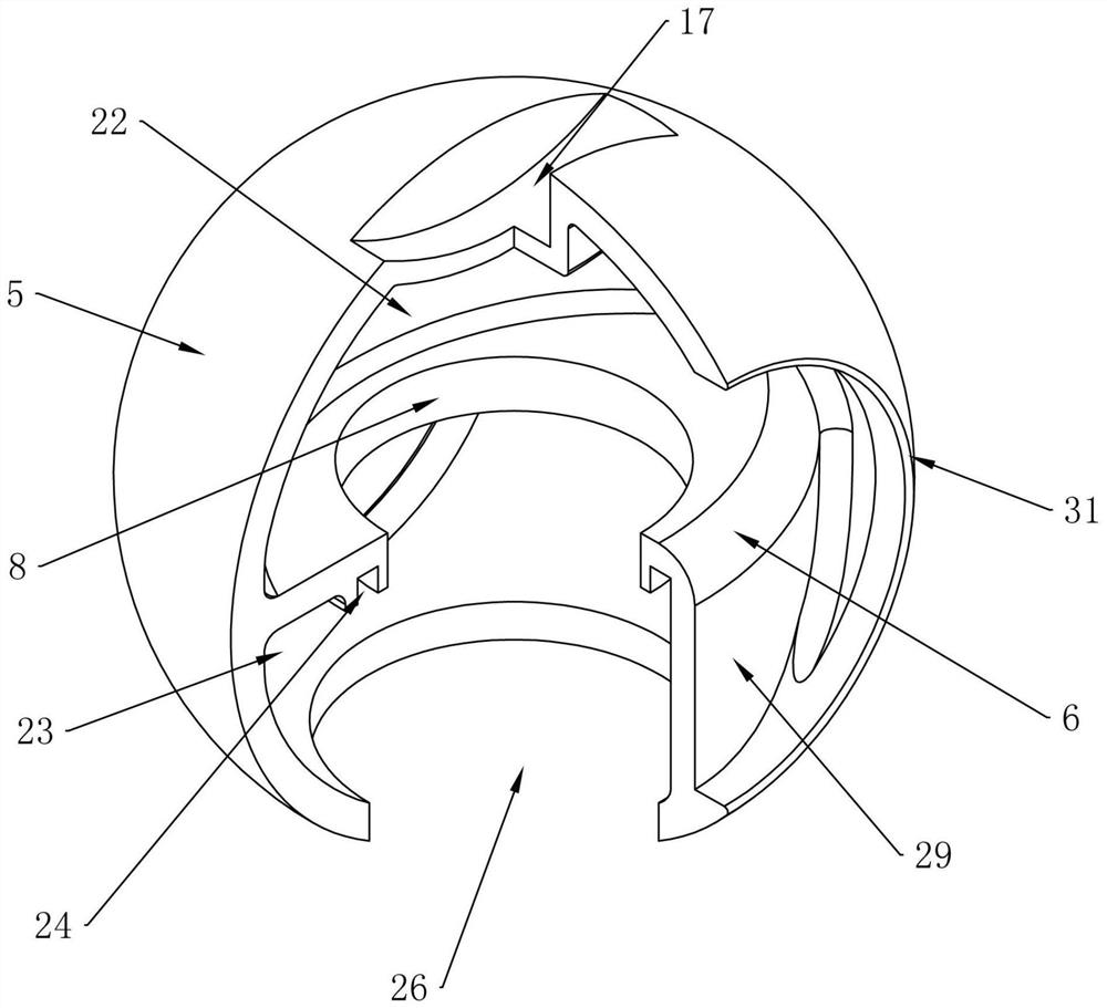
[0057] In a further embodiment of the present invention, the spool 5 includes: a sphere 27, a spacer 6, an upper connecting plate 28 and a lower connecting plate 29, the sphere 27 is a hollow structure, and one side of the sphere 27 is provided with an upper connecting plate that communicates with the inlet 3. Cavity inlet 31, the other side of spheroid 27 is provided with the lower cavity outlet 32 ​​that is communicated with outlet 4, and flow hole 8 is offered at the spacer 6 place, and spacer 6 is located at the inside of spheroid 27, and the upper connecting plate 28 The upper end and the left and right ends are all connected with the inwall of the spheroid 27, the lower end of the upper connecting plate 28 is connected with one side of the outer edge of the shelf 6, and the lower end and the left and right end...


PUM


Abstract

The invention discloses a filter ball valve. The valve comprises a valve body and a valve element rotatably arranged in the valve body, wherein the valve body is provided with an inlet and an outlet,and the valve element is provided with an upper cavity, a lower cavity and a circulating hole communicating with the upper cavity and the lower cavity, wherein the upper cavity communicates with the inlet, and the lower cavity communicates with the outlet; and the valve further comprises a filter screen, at least one part of the filter screen is arranged in the lower cavity, the filter screen is detachably connected with the valve element, and at least one part of the filter screen is arranged between the lower cavity and the outlet. According to the valve, the filter screen can be replaced from an end cover, so that pollution discharge cleaning is convenient, and the pollution discharge filtering effect of impurities is good.

Description

technical field [0001] The invention relates to the technical field of valves, in particular to a filter ball valve. Background technique [0002] At present, in the civil or industrial fields, all kinds of water supply, heating, and gas supply pipeline systems are equipped with various measuring instruments and equipment and other components. As the use time increases, the impurities in various flowing media Accumulated in the pipeline and various parts used, causing pipeline blockage or component wear, affecting the accuracy of various measuring instruments and the service life of equipment. [0003] In order to solve these problems, various filtering devices and valves have been installed in the pipeline to filter and clean up the impurities accumulated in the pipeline during long-term use, so as to ensure the normal operation of instruments and equipment. [0004] Existing ordinary filter ball valves such as Patent No. 201280017999.X are formed by adding a filter to the...

Claims


Application Information

Patent Timeline
IPC IPC(8): F16K5/06F16K5/08F16K27/06F16K31/60F16K41/02B01D35/04
CPCF16K5/0663F16K5/08F16K27/067F16K31/60F16K41/02B01D35/04
Inventor 郭理军严荣杰蔡小飞
Owner NINGBO JIEKELONG PRECISION MFG
Why Eureka
Try Eureka