
Novel offshore wind power foundation structure and construction method thereof

An offshore wind power and infrastructure technology, which is applied in infrastructure engineering, construction, sheet pile walls, etc., can solve the problems that the construction unit has no wing sheet pile construction technology, the wing plate is not easy to transport, and the wing plate is twisted and deformed, so as to improve the rigidity. , Improve the horizontal bearing capacity, improve the effect of the force mode

Pending Publication Date: 2020-11-10
CHINA THREE GORGES CORPORATION
View PDF3 Cites 4 Cited by
  • Summary
  • Abstract
  • Description
  • Claims
  • Application Information

AI Technical Summary

Problems solved by technology

However, since the existing offshore wind power installation ships do not have the ability to directly install the wing sheet piles in the above technical solution, and the construction unit does not have a suitable construction technology for the wing sheet piles, at present, there is no successful application of the wing sheet piles in offshore wind farms at home and abroad. Engineering Demonstration
In addition, in the above-mentioned patent technical scheme, the size of the wing plate of the wing sheet pile is relatively large (the width of the wing plate is not less than 1 / 2 of the pile diameter, not greater than the pile diameter; the length of the wing plate is not less than the pile diameter, not more than three times the pile diameter ), the oversized wing plate is not easy to transport, and at the same time increases the difficulty of construction, and the wing plate is prone to distortion and deformation under the action of earth pressure

Method used


Image

  • Novel offshore wind power foundation structure and construction method thereof
  • Novel offshore wind power foundation structure and construction method thereof
  • Novel offshore wind power foundation structure and construction method thereof

Examples


Embodiment Construction

[0037] Embodiments of the present invention will be further described below in conjunction with the accompanying drawings.

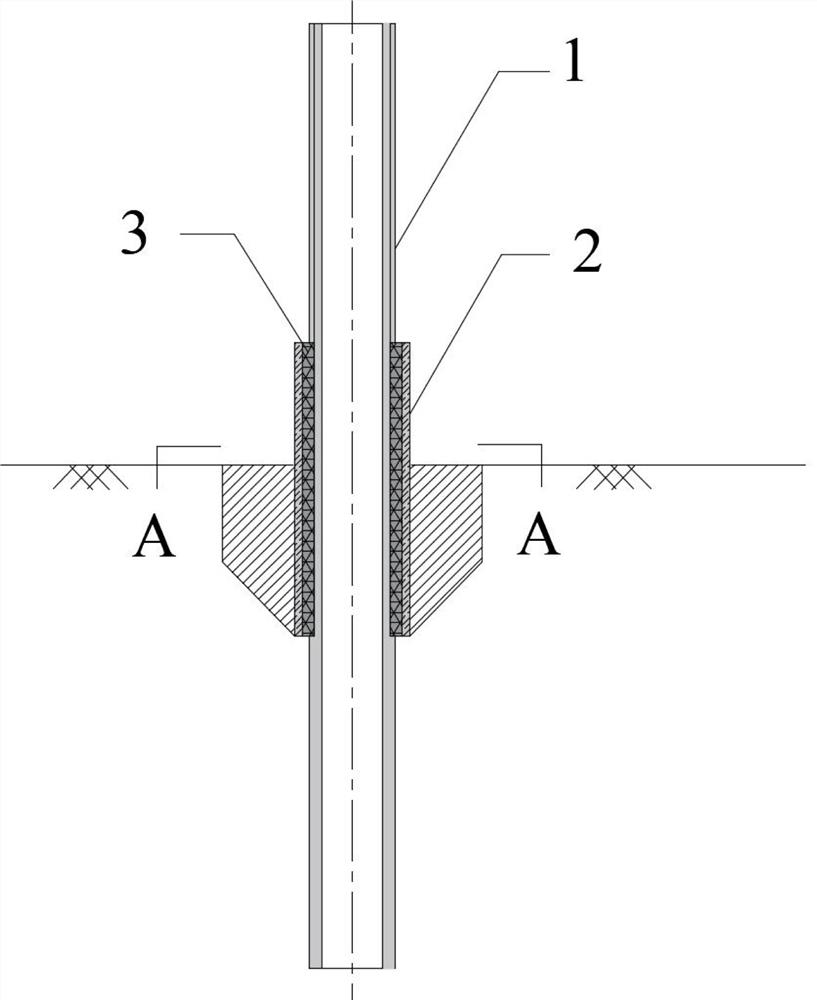
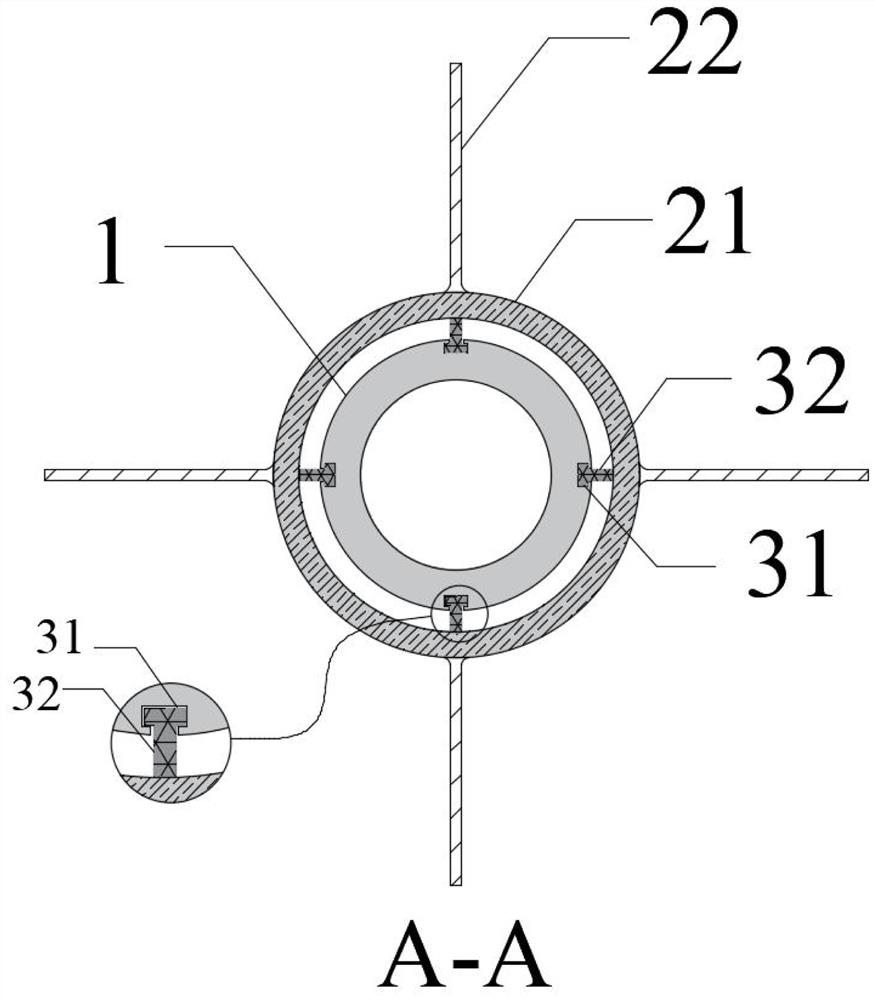
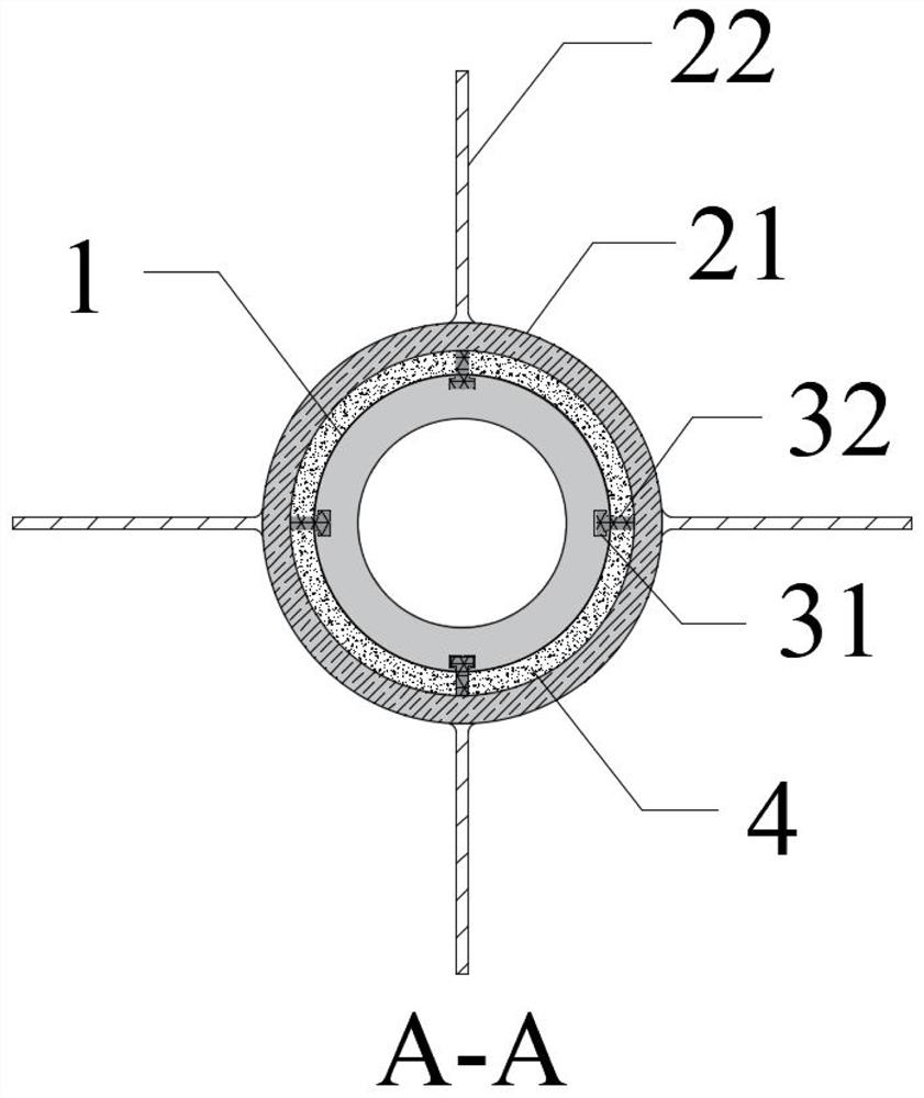
[0038] Refer to the attached Figure 1-7 Describe the new foundation structure of offshore wind power according to the embodiment of the present invention, including steel pipe pile 1, supporting structure 2, sliding device 3 and underwater self-protecting cementitious material 4, and the supporting structure 2 is connected with the steel pipe pile through sliding device 3 1 connection. The support structure 2 is composed of a sleeve 21 and a wing 22 , and the wing 22 is fixed on the outer wall of the sleeve 21 .

[0039] The outer wall of the steel pipe pile 1 is provided with a first connecting part 31 of a sliding device 3, and the inner wall of the casing 21 is provided with a second connecting part 32 of a sliding device 3, and the first connecting part 31 and the second connecting part 32 form a sliding guide. The sliding guide rail provides pos...


PUM


Abstract

The invention discloses a novel offshore wind power foundation structure and a construction method thereof. A supporting structure is composed of a sleeve and a wing plate, the supporting structure isinstalled on a steel pipe pile through a sliding device, and the supporting structure and the steel pipe pile are in sliding connection or fixed connection. The construction method of the novel offshore wind power foundation structure comprises the following steps that S1, pile sinking equipment is used for piling; S2, the supporting structure is hoisted and penetrates through the steel pipe pilethrough a sliding device to extend into a seabed foundation; S3, the supporting structure is driven to the designed depth through an auxiliary sleeve; and S4, the auxiliary sleeve is recycled, and subsequent procedures are conducted according to engineering requirements. Additional horizontal resistance provided by the supporting structure is used for improving the horizontal bearing capacity ofthe foundation structure, the size of the wing plate is reduced through the sleeve, the manufacturing, transporting and installing difficulty of the foundation structure is reduced through the supporting structure and the steel pipe pile which are independent of each other, and the foundation structure is suitable for shallow covering layer sea areas and the ocean environment with the water depthbeing 35-50 m.

Description

technical field [0001] The invention relates to the technical field of offshore wind power, in particular to a new offshore wind power foundation structure and a construction method thereof. Background technique [0002] Wind power is an important part of clean energy. Offshore wind power has the characteristics of high wind speed, stable wind speed, and large single-unit capacity. At present, the foundation types of offshore wind turbines include single pile foundation, jacket foundation, floating foundation and so on. Because the single pile foundation has the advantages of strong adaptability to seabed terrain, fast construction speed, and low construction cost, it accounts for more than 80% of the foundation types of offshore wind farms built in the world. [0003] During the operation of offshore wind turbines, the single pile foundation bears horizontal loads generated by wind, breaking waves, ocean currents, and sea ice. Under the action of horizontal cyclic loads, t...

Claims


Application Information

Patent Timeline
Patent Type & Authority Applications(China)
IPC IPC(8): E02D27/42E02D27/52E02D7/00E02D5/28E02D5/60
CPCE02D5/285E02D5/60E02D7/00E02D27/425E02D27/525
Inventor 王卫闫俊义
Owner CHINA THREE GORGES CORPORATION
Learn More