Raising needling machine with net inlet having brush cleaning function

An acupuncture machine and cleaning technology, which is applied to cleaning methods and appliances, dust removal, textiles and papermaking, etc., can solve the problems of increased inspection workload, many action transmission links, and increased energy consumption, so as to reduce daily inspection. The effect of less nursing workload, fewer action transmission links, and reasonable positions

Pending Publication Date: 2020-11-10
JIANGSU YINGYANG NONWOVEN MASCH CO LTD
View PDF16 Cites 0 Cited by
  • Summary
  • Abstract
  • Description
  • Claims
  • Application Information

AI Technical Summary

Problems solved by technology

[0004] Based on the reading of the above-mentioned patent documents on the napping needle loom and combined with professional knowledge, the following problems, which are undesirable but objectively unavoidable, often appear during the acupuncture process: First, the short fibers will accumulate Between the brush filaments of the brush that constitutes the brush curtain; the second is that the short fibers will wrap around the brush filaments
But the aforementioned brush cleaning device that this patent involves has the following technical problems: one, because the position of the device on one side of the frame is below the side of the brush curtain facing the net inlet, it is far away from the bottom corner of the brush curtain. The distance between the brush cleaning device and the brush curtain is relatively long, and the stability and reliability of the brush cleaning action by the scraper will be affected to a certain extent; The stability of the brush cleaning action makes the structure of the whole brush cleaning device more complicated and there are many action transmission links. Increased energy consumption, third, due to the complex structure of the brush cleaning device and the large overall volume, it will also have an adverse effect on the simplicity of the structure of the pile knitting machine

Method used


Image

  • Raising needling machine with net inlet having brush cleaning function
  • Raising needling machine with net inlet having brush cleaning function
  • Raising needling machine with net inlet having brush cleaning function

Examples


Embodiment Construction

[0022] In order to be able to understand the technical essence and beneficial effects of the present invention more clearly, the applicant will describe in detail in the form of examples below, but the description of the examples is not a limitation to the solution of the present invention. Anything made according to the concept of the present invention All equivalent transformations that are merely formal rather than substantive should be regarded as the scope of the technical solution of the present invention.

[0023] In the following description, all concepts related to the directionality or orientation of up, down, left, right, front, and back are based on the positional state of the picture, and therefore cannot be understood as providing for the present invention Special limitations of technical solutions.

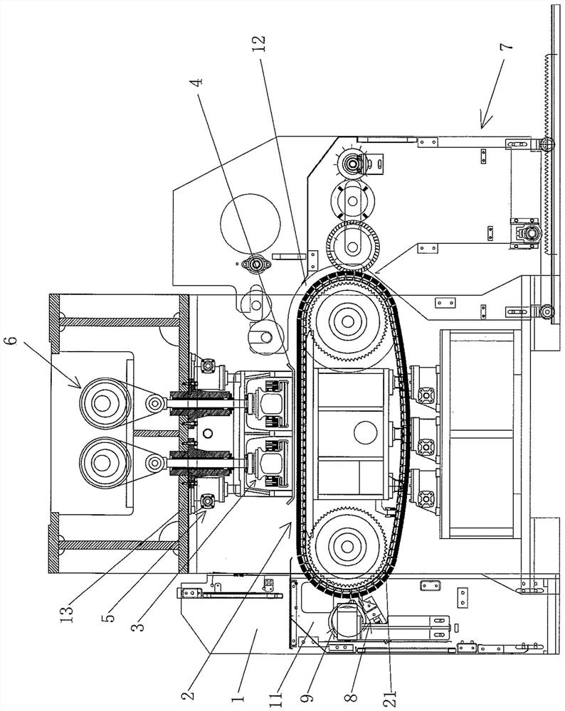
[0024] See figure 1 , Shows the frame 1, the raising mechanism 2, the needle punching mechanism 3, the stripping plate 4, the stripping plate lifting and adjusting mecha...


PUM


Abstract

The invention relates to a raising needling machine with a net inlet having a brush cleaning function. The raising needling machine comprises a rack, a raising mechanism, a needling mechanism, a net stripping plate, a net stripping plate lifting adjusting mechanism, a needle beam driving mechanism, a traction mechanism and a brush cleaning device. The net inlet is formed in the left side of the rack, a net outlet is formed in the right side of the rack, and the needle beam driving mechanism is arranged at the top of the rack; and the needling mechanism is connected with the needle beam drivingmechanism, the raising mechanism is arranged on the rack, the net stripping plate is connected with the net stripping plate lifting adjusting mechanism, and the net stripping plate lifting adjustingmechanism is arranged at the side, facing the raising mechanism, of a middle cross beam of the rack. The raising needling machine is characterized in that a brush cleaning device comprises a pair of acting cylinder fixing plates, a pair of acting cylinders, a scraper fixing arm and a scraper; the pair of acting cylinder fixing plates are fixed on face-to-face wall bodies of the rack, the pair of acting cylinders are fixed on the opposite sides of the pair of acting cylinder fixing plates, the scraper fixing arm is fixed with the tail ends of a pair of acting cylinder columns, and the scraper is fixed with the scraper fixing arm. The stability and the reliability of the brush cleaning action are reflected.

Description

Technical field [0001] The invention belongs to the technical field of non-woven machinery, and in particular relates to a napping needle punch with a net inlet with a brush cleaning function. Background technique [0002] The aforementioned raising needle punching machine is also called a jacquard raising needle punching machine, a raising jacquard needle punching machine or a needle punching jacquard raising machine. Needling machines are well-known in the industry, and many are found in published Chinese patent documents, such as CN101492861B (automated multifunctional needling machine), CN102373579B (endless needling machine), CN102677397B (structure improvement) Double-shaft needling machine), CN102677398A (double-shaft needling machine), CN102808290B (drum type needling machine), CN106087258B (double-sided butt-needling machine), CN105734836A (a low-noise needling machine), CN106087259A ( A high-speed dual-axis guided ex-situ needle punching machine) and CN106988023A (a sm...

Claims


Application Information

Patent Timeline
Patent Type & Authority Applications(China)
IPC IPC(8): D06C11/00B08B15/04
CPCB08B15/04D06C11/00
Inventor 范立元
Owner JIANGSU YINGYANG NONWOVEN MASCH CO LTD
Why Eureka
Try Eureka