Traffic control method and system
A flow control and flow technology, applied in the computer field, can solve problems such as poor defense effect
- Summary
- Abstract
- Description
- Claims
- Application Information
AI Technical Summary
Problems solved by technology
Method used
Image

Examples
Embodiment 1
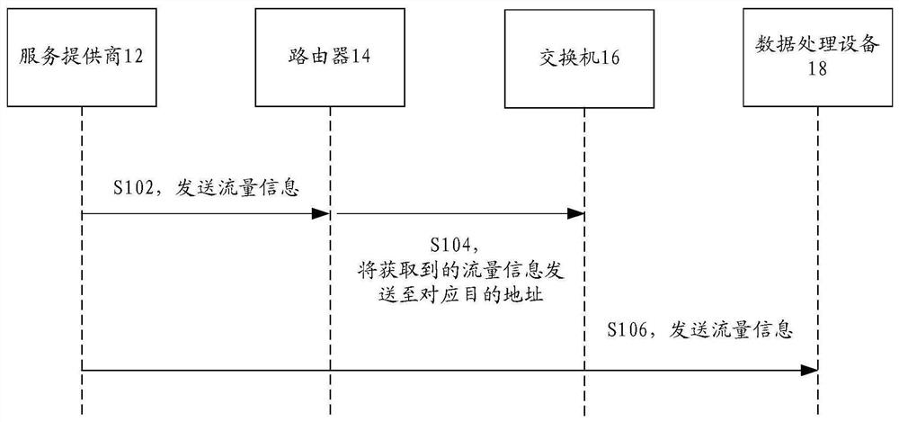
[0029] This application provides figure 1 The timing diagram of the flow control method shown, figure 1 is a sequence diagram of a flow control method according to Embodiment 1 of the present application, and the method includes the following processing flow:
[0030] Step S102, the service provider 12 sends traffic information to the router 14;
[0031] Specifically, the service provider 12 is used to send traffic information to the destination address, and the service provider 12 may be a search engine ISP, an instant messaging ISP, a mobile Internet service ISP, a portal ISP, or an email service provider. Wherein, there may be one or more service providers 12, and in addition, the address of the service provider 12 sending traffic information is the source address.
[0032] Step S104, the router 14 sends the obtained flow information to the switch 16 corresponding to the destination address;
[0033] Specifically, the destination address is the address of the receiving d...
Embodiment 2
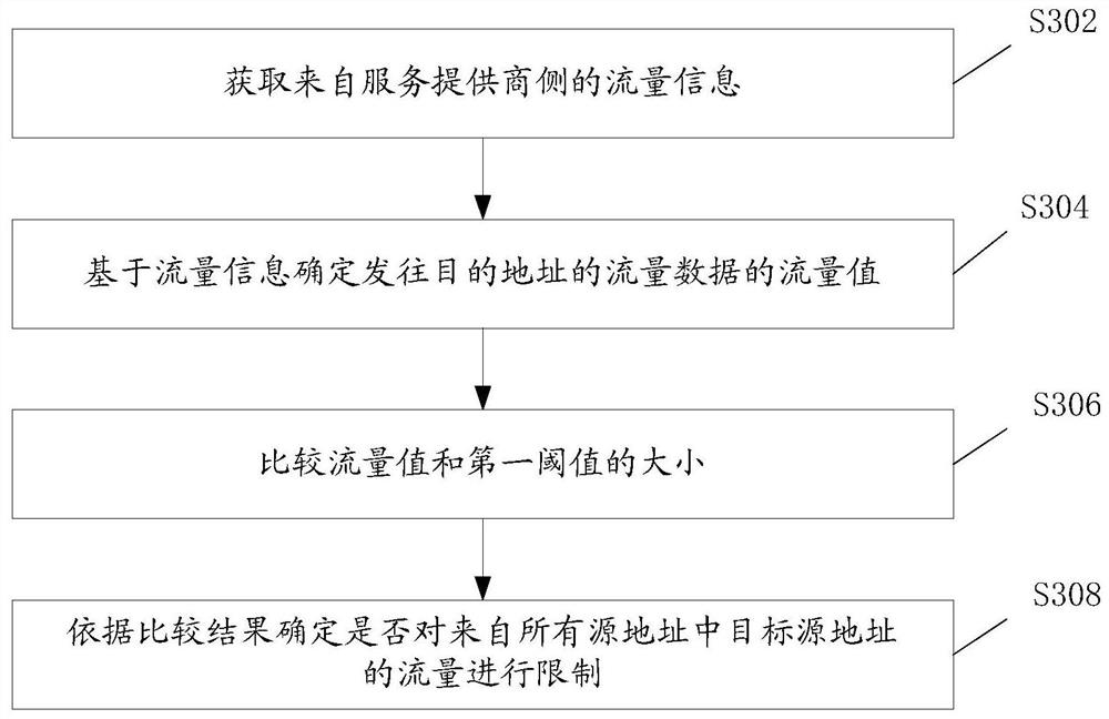
[0080] According to the embodiment of the present application, it also provides Figure 4 shown in the flow control method, Figure 4 It is a schematic flowchart of the flow control method, which at least includes the following steps S402 to S406:
[0081] Step S402, obtaining traffic information from all source addresses;
[0082] In some optional embodiments of the present application, the above-mentioned source address is an address for sending traffic data to a destination address.
[0083] Specifically, the source address above can be the address of an ISP. At present, according to the main business division, Chinese ISPs mainly fall into the following categories: search engine ISPs, instant messaging ISPs, mobile Internet service ISPs, portal ISPs, and email service providers. The flow information includes the flow value of the current flow.
[0084] In some optional embodiments of the present application, the real-time network traffic data can be acquired from the IS...
Embodiment 3
[0109] According to the embodiment of the present application, it also provides Figure 6 shown in the flow control method, Figure 6 It is a schematic flow chart of the flow control method, which at least includes the following steps S602 to S616:
[0110] Step S602, summarizing traffic data according to the destination IP;
[0111] Specifically, the destination IP address is the destination address for receiving traffic data; the traffic data may originate from the service provider side;
[0112] Step S604, judging whether the flow value of the flow data exceeds a first threshold;
[0113] If yes, execute step S606, if not, execute step S614;
[0114] Optionally, the traffic value is used to indicate the total traffic size from all source addresses of the traffic data;
[0115]Step S606, judging whether the above-mentioned flow value is being suppressed; if yes, execute step S616, if not, execute step S608;
[0116] Step S608, the source IP of the destination IP summari...
PUM
 Abstract
Description
Claims
Application Information
 - R&D
- Intellectual Property
- Life Sciences
- Materials
- Tech Scout
- Unparalleled Data Quality
- Higher Quality Content
- 60% Fewer Hallucinations
Browse by: Latest US Patents, China's latest patents, Technical Efficacy Thesaurus, Application Domain, Technology Topic, Popular Technical Reports.
© 2025 PatSnap. All rights reserved.Legal|Privacy policy|Modern Slavery Act Transparency Statement|Sitemap|About US| Contact US: help@patsnap.com