
Capacity configuration method for energy storage participating in peak regulation based on double-layer model

A technology of capacity allocation and energy storage, applied in energy storage, circuit devices, AC networks with energy trade/energy transmission authority, etc., can solve problems such as reducing the rationality and accuracy of energy storage system configuration

Active Publication Date: 2020-11-06
浙江华云清洁能源有限公司
View PDF12 Cites 1 Cited by
  • Summary
  • Abstract
  • Description
  • Claims
  • Application Information

AI Technical Summary

Problems solved by technology

[0003] Configuring energy storage systems in wind power high-permeability grids can effectively improve grid peak regulation pressure and increase grid wind power capacity, but the configuration of energy storage systems affects the effect of energy storage participating in peak regulation and its economy, so it is necessary to design energy storage reasonably The configuration strategy of system operation makes it take into account both peak shaving technology and economy
However, the current research on energy storage configuration does not take into account the optimization of energy storage charging and discharging power and the net income in the whole life cycle, therefore, it will reduce the rationality and accuracy of energy storage system configuration

Method used


Image

  • Capacity configuration method for energy storage participating in peak regulation based on double-layer model
  • Capacity configuration method for energy storage participating in peak regulation based on double-layer model
  • Capacity configuration method for energy storage participating in peak regulation based on double-layer model

Examples


Embodiment Construction

[0059] The following will clearly and completely describe the technical solutions in the embodiments of the application with reference to the drawings in the embodiments of the application. Apparently, the described embodiments are only some of the embodiments of the application, not all of them. Based on the embodiments in this application, all other embodiments obtained by persons of ordinary skill in the art without making creative efforts belong to the scope of protection of this application.

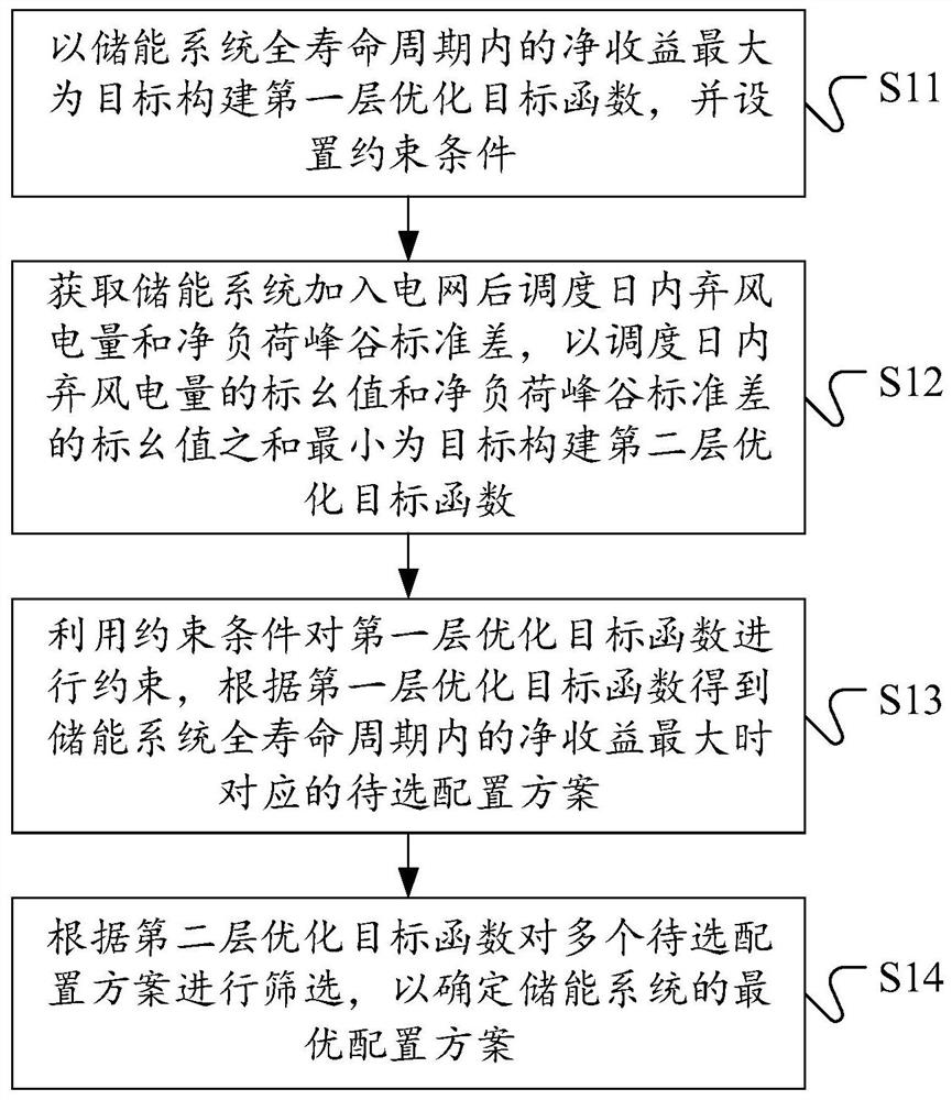
[0060] see figure 1 , which shows a flow chart of a capacity configuration method for energy storage participating in peak shaving based on a two-layer model provided by an embodiment of the present application. Capacity allocation methods, which can include:

[0061] S11: Construct the first-level optimization objective function with the goal of maximizing the net income in the entire life cycle of the energy storage system, and set constraints.

[0062] When deploying an energy ...


PUM


Abstract

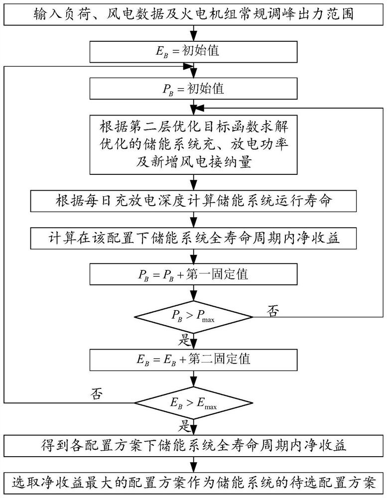
The invention discloses a capacity configuration method, device and equipment for energy storage participating in peak regulation based on a double-layer model and a computer readable storage medium.The method comprises the steps of: constructing a first-layer optimization objective function with the maximum net income in the whole life cycle of an energy storage system as the objective, and setting constraint conditions; constructing a second-layer optimization objective function by taking the minimum sum of the per-unit value of the wind curtailment electric quantity in the scheduling day and the per-unit value of the net load peak-valley standard deviation as an objective; constraining the first-layer optimization objective function by using a constraint condition, and obtaining a corresponding to-be-selected configuration scheme according to the first-layer optimization objective function; and screening the plurality of to-be-selected configuration schemes according to the second-layer optimization objective function, and determining an optimal configuration scheme of the energy storage system. According to the technical scheme, when the energy storage system participates in peak shaving, a good peak shaving effect can be achieved, good net income can be obtained, and therefore the rationality and accuracy of energy storage system configuration are improved.

Description

technical field [0001] The present application relates to the technical field of energy storage configuration, and more specifically, relates to a capacity configuration method, device, equipment and computer-readable storage medium for energy storage participating in peak shaving based on a two-layer model. Background technique [0002] In the current energy Internet, how to improve energy utilization and promote the consumption of renewable energy is a current research hotspot. Taking wind power as an example, with the continuous increase in the penetration rate of renewable energy such as wind power, the economic problems caused by wind curtailment are still relatively serious. In order to solve the above peak shaving problem, it is necessary to give full play to the peak shaving capability of the thermal power unit, but making the unit enter the deep peak shaving stage or even the start-stop peak shaving stage will increase the operating loss of the unit and reduce its e...

Claims


Application Information

Patent Timeline
IPC IPC(8): H02J3/28H02J3/32H02J3/38
CPCH02J3/28H02J3/32H02J3/008H02J3/381H02J2203/10H02J2203/20H02J2300/28Y02E70/30
Inventor 沈宝兴林琳徐一剑陈琦张谓江吴星昂於国芳吕浩华吴慧青俞梅李军徽李翠萍张嘉辉张昊马得轩严干贵
Owner 浙江华云清洁能源有限公司
Learn More