
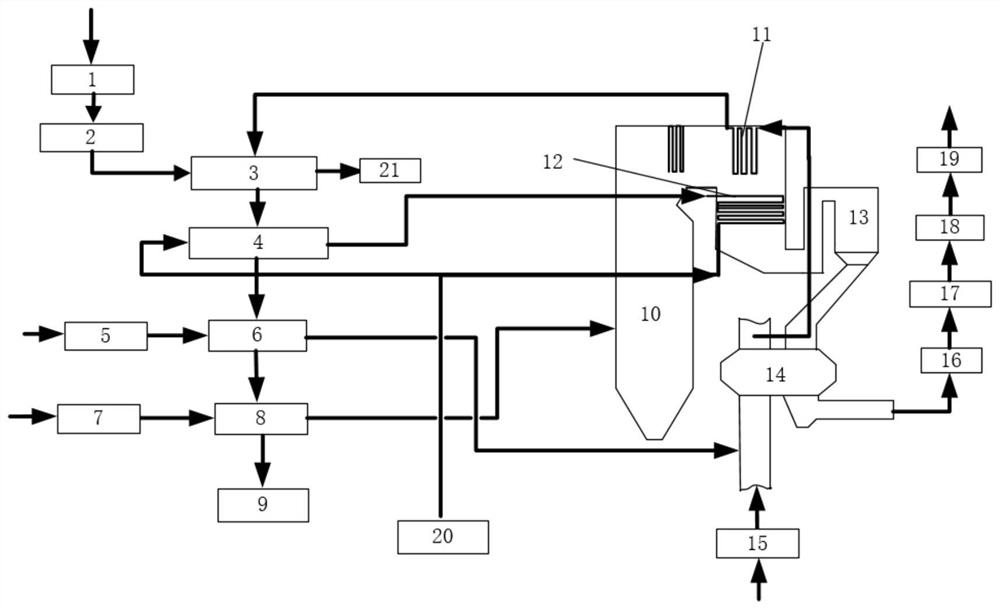
Garbage disposal and generator set coupling power generation system

A waste treatment system and generating set technology, applied in the direction of machines/engines, mechanical equipment, steam engine devices, etc., can solve the problems of high investment cost, large consumption of non-renewable energy, high power generation cost, etc., and achieve low pollutant emission concentration, energy The effect of high utilization efficiency and low thermal ignition loss rate of residue

Pending Publication Date: 2020-11-06
YANTAI LONGYUAN POWER TECH +1
View PDF0 Cites 3 Cited by
  • Summary
  • Abstract
  • Description
  • Claims
  • Application Information

AI Technical Summary

Problems solved by technology

Conventional waste incineration technology has complex systems, high investment costs, high operating costs, and low energy utilization efficiency. At the same time, there are certain requirements for the calorific value of waste. The waste needs to be sorted, fermented and stored for a certain period of time before it can be used for incineration.
In the process of waste incineration, waste incineration plants need to configure complex flue gas purification systems separately for the pollutants such as dioxins, chlorides, sulfur dioxide, and nitrogen oxides. This flue gas purification system requires large investment and high energy consumption. , The purification efficiency is low, which will adversely affect the economic operation of the waste incineration power plant
[0003] In addition, at this stage, traditional thermal power generating units only rely on non-renewable energy for power generation, which is costly and consumes a lot of non-renewable energy. However, the traditional power generation system is relatively mature and complete, equipped with boilers and flue gas treatment devices and other equipment

Method used


Image

  • Garbage disposal and generator set coupling power generation system

Examples


Embodiment Construction

[0024] The present invention will be further described in detail below in conjunction with the accompanying drawings and embodiments. It should be understood that the specific embodiments described here are only used to explain the present invention, but not to limit the present invention. In addition, it should be noted that, for the convenience of description, only some structures related to the present invention are shown in the drawings but not all structures.

[0025] In the description of the present invention, unless otherwise clearly specified and limited, the terms "connected", "connected" and "fixed" should be understood in a broad sense, for example, it can be a fixed connection, a detachable connection, or an integrated ; It can be a mechanical connection or an electrical connection; it can be a direct connection or an indirect connection through an intermediary, and it can be the internal communication of two components or the interaction relationship between two ...


PUM


Abstract

The invention belongs to the technical field of energy utilization and discloses a garbage disposal and generator set coupling power generation system which comprises a garbage disposal system and a thermal power generation system; the garbage disposal system comprises a garbage incinerator and a dust remover communicating with each other; the thermal power generation system comprises a boiler, afirst air pre-heater and a first heat exchanger; the first heat exchanger is arranged in a reversal chamber of the boiler and communicates with the garbage incinerator; the first air pre-heater communicates with the first heat exchanger; the dust remover communicates with the boiler; the flue gas through dedusting by the dust remover enters the boiler to burn; and the air enters the first heat exchanger via the first air pre-heater and is heated by heat generated through combustion in the boiler to enter the garbage incinerator. Compared with a conventional waste incineration power station, heat generated through garbage decomposition can be directly absorbed by a boiler system, and after the boiler treats waste incineration flue gas at the high temperature, dioxin and other exhaust gas inwaste incineration flue gas can reach the discharge standard of pollutants.

Description

technical field [0001] The invention relates to the technical field of energy utilization, in particular to a power generation system coupled with waste disposal and generator sets. Background technique [0002] At present, waste treatment technologies mainly include incineration, landfill and biological treatment, among which waste incineration is recognized as one of the important methods of waste resource treatment. Conventional waste incineration technology has complex systems, high investment costs, high operating costs, and low energy utilization efficiency. At the same time, there are certain requirements for the calorific value of waste. The waste needs to be sorted, fermented and stored for a certain period of time before it can be used for incineration. In the process of waste incineration, waste incineration plants need to configure complex flue gas purification systems separately for the pollutants such as dioxins, chlorides, sulfur dioxide, and nitrogen oxides. ...

Claims


Application Information

Patent Timeline
Patent Type & Authority Applications(China)
IPC IPC(8): F23G7/00F23G5/44F23G5/46F23L15/04F23J15/02F23J1/00F01K11/00
CPCF01K11/00F23G5/44F23G5/46F23G7/00F23J1/00F23J15/02F23J15/022F23L15/04Y02E20/34
Inventor 张勇赵俊伟张云龙黎尚全莫子孟孙伟晋葛茂杰房越杨天亮
Owner YANTAI LONGYUAN POWER TECH
Learn More