
A joint structure on a d-pillar

A technology of joint structure and joint connection, which is applied in the direction of upper structure, upper structure sub-assembly, vehicle parts, etc., which can solve the problems of many processes, long mold debugging time, high precision requirements, etc.

Active Publication Date: 2021-07-06
ZHEJIANG LEAPMOTOR TECH CO LTD
View PDF8 Cites 0 Cited by
  • Summary
  • Abstract
  • Description
  • Claims
  • Application Information

AI Technical Summary

Problems solved by technology

[0004] In the above technology, the joint on the D-pillar is in the form of a three-way joint, which still requires high precision, is difficult to process, has many procedures, and takes a long time for mold debugging.

Method used


Image

  • A joint structure on a d-pillar
  • A joint structure on a d-pillar
  • A joint structure on a d-pillar

Examples


Embodiment 1

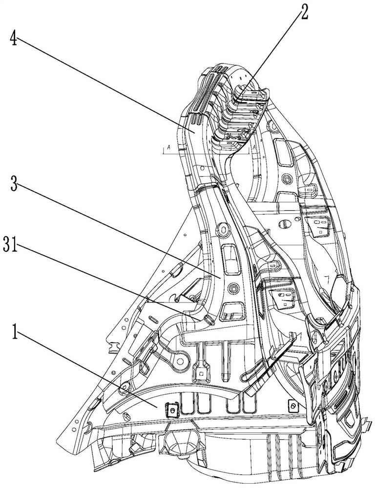
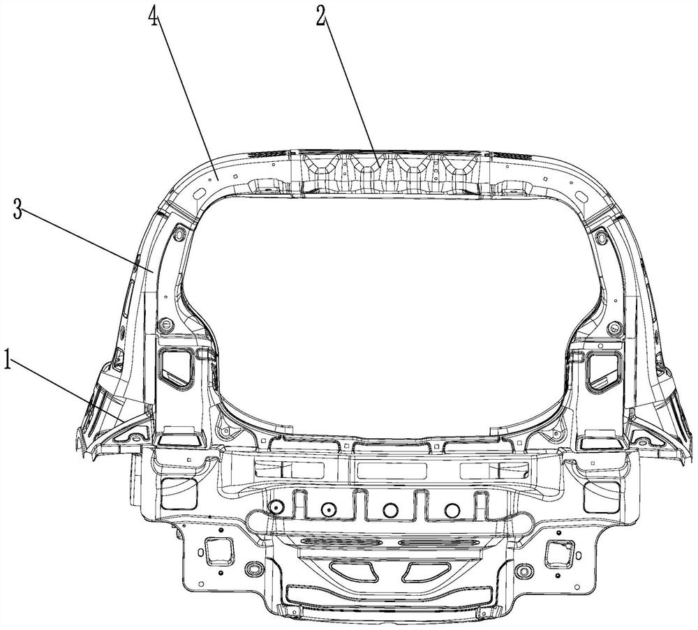
[0025] Embodiment 1: as figure 1 and image 3 as shown in

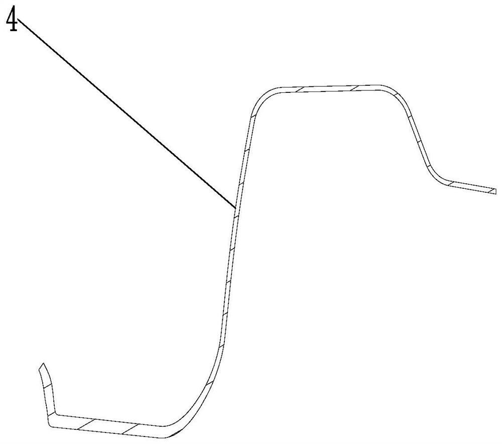
[0026] A D-pillar upper joint structure, including an outer wheel house 1, a rear roof beam 2, and a D-pillar reinforcement plate 3 arranged on a D-pillar 9. The D-pillar reinforcement plate is located at the left and right ends of the rear roof beam, and the upper and lower sides of the D-pillar reinforcement plate are The two ends are respectively connected with the rear roof beam and the outer wheel house. The upper end of the D-pillar reinforcement plate is connected with the rear roof beam through the D-pillar upper joint 4. There are two joints 41 on the D-pillar upper joint, one of which is connected to the rear roof beam, and the other One joint attaches to the D-pillar reinforcement. The present invention improves the joint structure on the D-pillar, adopts the two-joint structure, and greatly reduces the difficulty of stamping compared with the three-joint structure, greatly improves the precision and redu...

Embodiment 2

[0028] Embodiment 2: Based on the structure of the above-mentioned embodiment, such as Figure 4 as shown,

[0029] There is a buffer structure between the D-pillar upper joint and the D-pillar, and the buffer structure includes the airbag 5 on the D-pillar. The joints are used to cushion the connections at the joints. The buffer structure is conducive to the installation of the joints on the D-pillar. While ensuring sufficient torsional rigidity of the joints on the D-pillar, it can also prevent stress concentration. In addition, in the event of an unexpected collision, the buffer structure can provide force relief. The upper joint has a protective effect.

[0030]The D-pillar is provided with an air chamber, the airbag is located in the air chamber, the airbag is located below the joint, the air chamber is provided with an extruding plate 6 slidingly arranged, and the lower end of the joint on the D-pillar is provided with a downwardly protruding fixing plate 7, the fixing...


PUM


Abstract

The invention relates to the field of vehicle structures, in particular to a joint structure on a D-pillar. It includes the outer wheel house, the rear roof beam and the D-pillar reinforcement plate on the D-pillar. The D-pillar reinforcement plate is located at the left and right ends of the rear roof beam. The upper and lower ends of the D-pillar reinforcement plate are respectively connected with the rear roof beam and the outer wheel house. , the upper end of the D-pillar reinforcement plate is connected to the rear roof beam through the D-pillar upper joint, and the D-pillar upper joint has two joints, one of which is connected to the rear roof beam, and the other joint is connected to the D-pillar reinforcement plate. The present invention improves the joint structure on the D-pillar, adopts the two-joint structure, and greatly reduces the difficulty of stamping compared with the three-joint structure, greatly improves the precision and reduces the stamping process, and the mold requirements are correspondingly reduced.

Description

technical field [0001] The invention relates to the field of vehicle structures, in particular to a joint structure on a D-pillar. Background technique [0002] The joints on the D-pillar on the general vehicle models are mostly 3-way joints. The 3-way joint structure has always been a difficult point in stamping and assembly welding, because the three joints of the three-way structure are matching surfaces, which require high precision. The characteristics of the tee joint and the depth required to ensure the performance requirements here, the D-pillar three-joint is difficult to process, and generally requires additional processes and a long mold debugging time to basically guarantee the accuracy requirements. [0003] For example, the Chinese patent authorization announcement number CN209921435U, the authorized announcement date is 2020.01.10, and the name is "D-pillar upper joint structure", which discloses a D-pillar upper joint structure, including the D-pillar assembl...

Claims


Application Information

Patent Timeline
Patent Type & Authority Patents(China)
IPC IPC(8): B62D25/04
CPCB62D25/04
Inventor 刘建胜
Owner ZHEJIANG LEAPMOTOR TECH CO LTD
Learn More