


Quick Research
Generate reliable direction feasibility study reports for your R&D in just a few steps.

Technical Q&A
Discover and master advanced knowledge NOW. Basics, ideas, possibilities, all at once.

Find Solutions
As an expert in R&D theories, this can generate solutions to your technical problems instantly.

Evaluate Feasibility
Analyze your overall solution with one click, know your potential R&D risks in advance.

Monitor Landscape
Get weekly tech updates, stay abreast of the latest tech innovations and key insights.
Nanometer positioning control system for micro-displacement platform
A technology of nano-positioning and control system, applied in the direction of using optical devices, measuring devices, instruments, etc.
- Summary
- Abstract
- Description
- Claims
- Application Information
AI Technical Summary
Problems solved by technology
Method used
Image

Examples
specific Embodiment approach 1
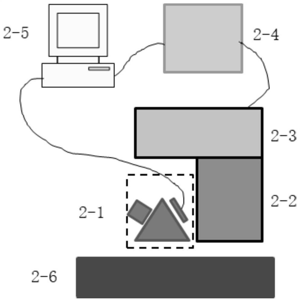
[0019] Specific embodiment one, combined with Figure 1-2 To explain this embodiment, a nano-positioning control system for a micro-displacement platform of this embodiment includes a positioning sensor 2-1, a scanning probe 2-2, a scanning platform 2-3, a controller 2-4, and a host computer 2. -5. The positioning sensor 2-1 and the scanning probe 2-2 are assembled together, the positioning sensor 2-1 is connected with the upper computer 2-5 through a signal line, and the scanning probe 2-2 is fixed on the scanning platform 2-3 , The scanning platform 2-3 and the controller 2-4 establish signal transmission to control the movement of the scanning platform 2-3, the controller 2-4 is connected with the upper computer 2-5, and the whole system constitutes a closed-loop control system of nano positioning. During the nano-positioning process, when the scanning probe 2-2 and scanning platform 2-3 are moved to the surface of the material to be measured 2-6 within 1 micron under the co...
specific Embodiment approach 2
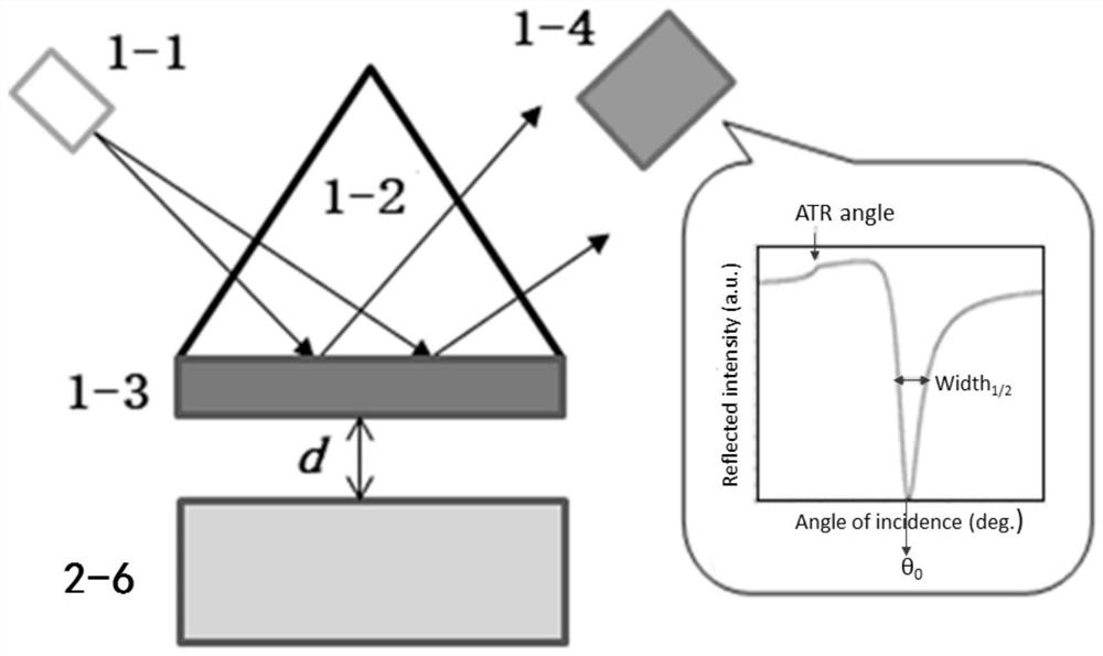
[0020] Specific implementation mode two, combined with Figure 1-2 This embodiment will be described. In this embodiment, a nano-positioning control system for a micro-displacement platform, the positioning sensor 2-1 includes a light source 1-1, a prism 1-2, a metal film 1-3 and a light intensity receiver 1-4, the working surface of the prism 1-2 is plated with a metal film 1-3, the light source 1-1 emits laser light incident on the metal film 1-3 through the prism 1-2, the metal film 1-3 reflects the light source 1-1 The laser light is received by the light intensity receiver 1-4. In this way, the nano positioning sensor 2-1 is a positioning sensor. Its working principle is that when the incident light wave vector matches the surface plasmon wave (SPW) wave vector of the metal coating (gold or silver) on the prism surface, the reflected light intensity will be Suddenly decrease. The present invention regards the air layer between the scanning probe and the surface of the ma...
specific Embodiment approach 3
[0021] Specific implementation mode three, combined with Figure 1-2 To illustrate this embodiment, in a nano-positioning control system for a micro-displacement platform of this embodiment, the metal film 1-3 is a gold film or a silver film.
PUM
| Property | Measurement | Unit |
|---|---|---|
| thickness | aaaaa | aaaaa |
| thickness | aaaaa | aaaaa |
| thickness | aaaaa | aaaaa |
Abstract
Description
Claims
Application Information
 - R&D Engineer
- R&D Manager
- IP Professional
- Industry Leading Data Capabilities
- Powerful AI technology
- Patent DNA Extraction
Browse by: Latest US Patents, China's latest patents, Technical Efficacy Thesaurus, Application Domain, Technology Topic, Popular Technical Reports.
© 2024 PatSnap. All rights reserved.Legal|Privacy policy|Modern Slavery Act Transparency Statement|Sitemap|About US| Contact US: help@patsnap.com