Plasma sterilization and purification device

A plasma and purification device technology, applied in the field of air purification, can solve the problems of failure to perform air purification, sterilization and disinfection, failure of air purification equipment to purify air, and increase of purification equipment costs, so as to improve the sterilization and purification effect and reduce the cost of air purification. Minimize the frequency of brush replacement and prolong the service life

Pending Publication Date: 2020-11-03
安徽颐雅科技有限公司
View PDF0 Cites 2 Cited by
  • Summary
  • Abstract
  • Description
  • Claims
  • Application Information

AI Technical Summary

Problems solved by technology

[0003] In the existing air purifier, in order to enhance the purifying effect of the purifier on the air, multiple filters of different levels are placed in the purification equipment, which not only increases the production cost of the purification equipment, but also prevents the particle pollutants that are invisible to the naked eye. It can be discharged through the filter screen, causing the air purification equipment to fail to purify the air effectively
[0004] An air purification and disinfection device provided in the application number 2016112536659, through the first filter screen, glass cover and ultraviolet lamp, the second filter screen and the third filter screen, the multi-layer filter screen filters the dust particles in the air, Moreover, the air purification and disinfection device not only increases the cost of purification equipment production, but also can still discharge through the filter screen for particulate pollutants that are invisible to the naked eye, and fails to play the role of air purification, sterilization and disinfection.

Method used


Image

  • Plasma sterilization and purification device
  • Plasma sterilization and purification device
  • Plasma sterilization and purification device

Examples


Embodiment Construction

[0020] In order to make the technical means, creative features, goals and effects achieved by the present invention easy to understand, the present invention will be further elaborated below in conjunction with the embodiments.

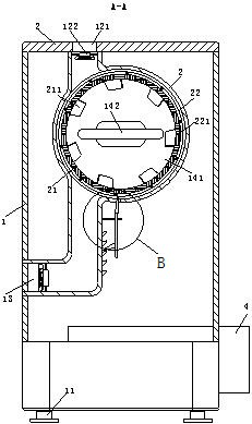
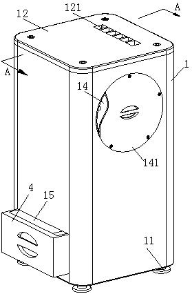
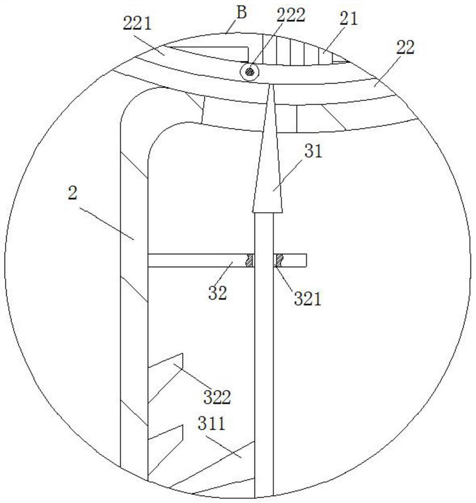
[0021] Such as Figure 1 to Figure 3 As shown, a plasma sterilization and purification device according to the present invention includes a housing 1; the four right angles of the lower end surface of the housing 1 are provided with threaded support legs 11, and the upper end of the housing 1 is provided with bolts The connected end cover 12 has an air inlet 121 on one side of the end cover 12, and a fan 122 for air extraction is provided in the air inlet 121, and an air outlet 13 is provided on the side wall of the housing 1, and an exhaust air is provided in the air outlet 13. A fan 122, and a chamber 2 for air purification is provided between the air outlet 13 and the air inlet 121; the upper port of the chamber 2 is communicated with the air inlet...


PUM


Abstract

The invention belongs to the field of air purification, and particularly relates to a plasma sterilization and purification device which comprises a shell. Supporting legs in threaded connection are arranged at the four right-angle positions of the lower end face of the shell, an end cover in bolted connection is arranged at the upper end of the shell, an air inlet is formed in one side of the endcover, a fan used for exhausting air is arranged in the air inlet, an air outlet is formed in one side wall of the shell, and a fan used for exhausting air is arranged in the air outlet; a cavity forair purification is formed between the air outlet and the air inlet; an upper port of the cavity communicates with the air inlet, a lower port of the cavity communicates with the air outlet, and a cylindrical filter screen is arranged in a circular space in the cavity; and a through groove is formed in one side wall of the shell, the through groove is opposite to a circular cavity of the cavity,a circular push plate is arranged at a groove opening of the through groove and fixedly connected to the groove opening of the through groove through screws, a handle is arranged on the side wall, located outside the shell, of the push plate, and a plasma generator is arranged in the center of the side wall, located in the shell, of the push plate.

Description

technical field [0001] The invention belongs to the field of air purification, in particular to a plasma sterilization and purification device. Background technique [0002] Plasma air purification technology integrates multiple functions such as sterilization, dust removal, decomposition of formaldehyde and TVOC, and has broad application prospects in many fields [0003] In the existing air purifier, in order to enhance the purifying effect of the purifier on the air, multiple filters of different levels are placed in the purification equipment, which not only increases the production cost of the purification equipment, but also prevents the particle pollutants that are invisible to the naked eye. It can be discharged through the filter, causing the air purification equipment to fail to effectively purify the air. [0004] An air purification and disinfection device provided in the application number 2016112536659, through the first filter screen, glass cover and ultravio...

Claims


Application Information

Patent Timeline
Patent Type & Authority Applications(China)
IPC IPC(8): F24F3/16F24F13/28
CPCF24F3/16F24F13/28
Inventor 吴志强
Owner 安徽颐雅科技有限公司
Why Eureka
Try Eureka