
Outburst prevention drilling machine boosting device

A drilling rig and boosting technology, applied in safety devices, support devices, drilling equipment, etc., can solve the problems of large deviation of construction drilling angle, large hole forming error, low construction efficiency, etc., so as to reduce the occurrence of employee injury accidents. Probability, the effect of improving stability

Pending Publication Date: 2020-11-03
重庆能投渝新能源有限公司
View PDF0 Cites 0 Cited by
  • Summary
  • Abstract
  • Description
  • Claims
  • Application Information

AI Technical Summary

Problems solved by technology

[0002] When constructing anti-outburst drilling in coal mines, due to the limitation of anti-outburst construction equipment, hand-held anti-outburst drilling rigs (such as coal electric drills, emulsion drilling rigs, pneumatic drilling rigs, etc.) are generally used. The sudden drilling tool is used to push the drilling rig into the coal body by manpower. Due to the large torque of the drilling rig, during the construction process, the drilling tool will flip over and hurt the hands and feet of the construction workers; during the construction of the coal seam, toxic and harmful gases will be ejected and cause harm to the construction workers; The drilling angle deviation of the drilling rig is relatively large, which often causes skewing, large hole forming errors, and often not in place; the large torsion of the drilling rig consumes a lot of physical strength for employees, is prone to fatigue, and the construction efficiency is low. Therefore, a new coal mine drilling rig is urgently needed to solve the problem. There are technical problems in the technology

Method used


Image

  • Outburst prevention drilling machine boosting device
  • Outburst prevention drilling machine boosting device
  • Outburst prevention drilling machine boosting device

Examples


Embodiment Construction

[0026] The following describes the embodiments of the present invention in detail. Examples of the embodiments are shown in the accompanying drawings, wherein the same or similar reference numerals indicate the same or similar elements or elements with the same or similar functions. The following embodiments described with reference to the accompanying drawings are exemplary, and are only used to explain the present invention, and cannot be understood as a limitation to the present invention.

[0027] In the description of the present invention, it should be understood that the terms "center", "longitudinal", "transverse", "length", "width", "thickness", "upper", "lower", "front", " "Back", "Left", "Right", "Vertical", "Horizontal", "Top", "Bottom", "Inner", "Outer", "Clockwise", "Counterclockwise" and other directions or The positional relationship is based on the position or positional relationship shown in the drawings, and is only for the convenience of describing the present...


PUM


Abstract

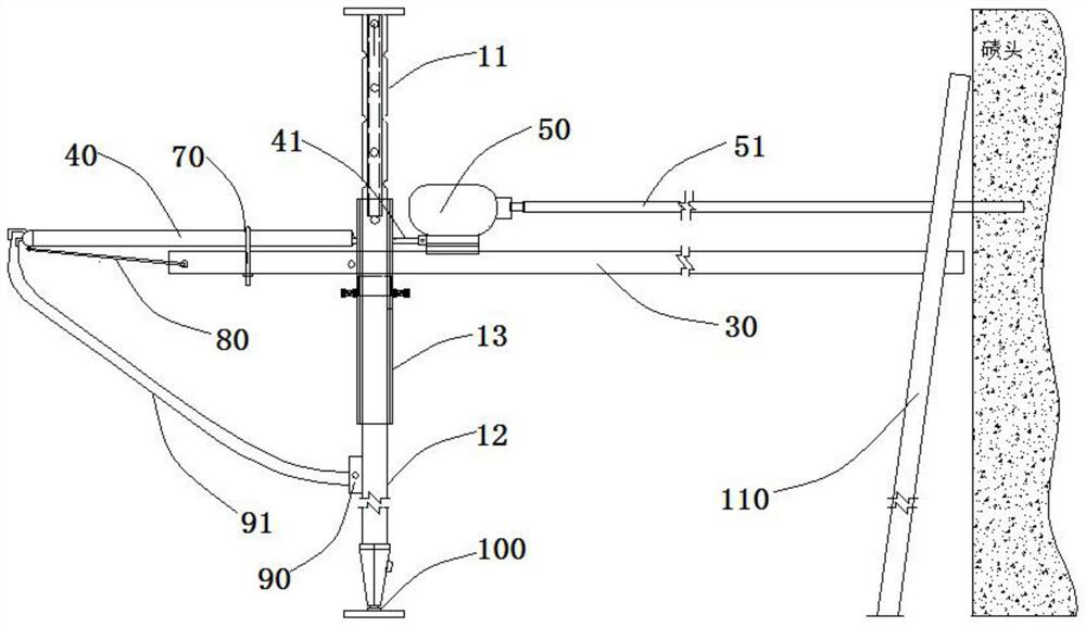
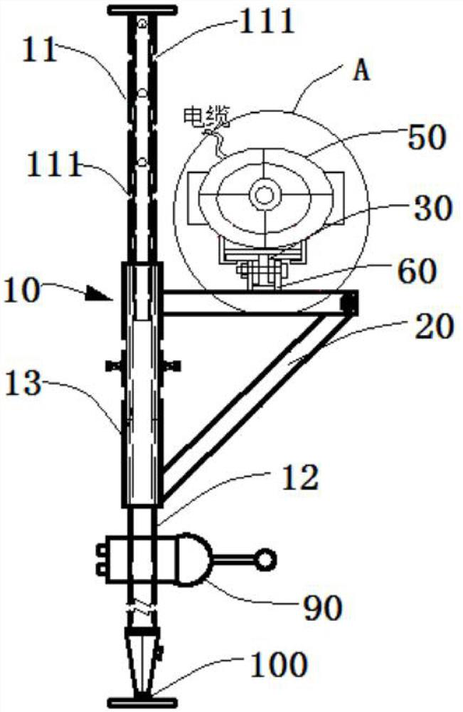
The invention provides an outburst prevention drilling machine boosting device which comprises a lifting cylinder, a supporting frame, a drilling machine bracket, a booster and an electric drill. A drill rod is arranged at the front end of the electric drill, the supporting frame is fixed to the lifting cylinder, the drilling machine bracket is fixed to the upper end of the supporting frame, and asliding way allowing the electric drill to slide is arranged on the drilling machine bracket; the lifting cylinder comprises a first-stage sleeve, a second-stage sleeve and a third-stage sleeve, thethird-stage sleeve is arranged between the first-stage sleeve and the second-stage sleeve, the diameter of the third-stage sleeve is larger than that of the first-stage sleeve and that of the second-stage sleeve, and a plurality of round holes are evenly formed in each of the first-stage sleeve, the second-stage sleeve and the third-stage sleeve; and steel bars are inserted into the round holes tolimit the relative positions between the third-stage sleeve and the first-stage sleeve and between the third-stage sleeve and the second-stage sleeve. According to the outburst prevention drilling machine boosting device, a drilling machine is fixed to the drilling machine bracket, and equipment is fixed stably and is not prone to turning over, so that the stability of the equipment is improved,and the probability of staff injury accidents is reduced.

Description

Technical field [0001] The invention relates to the technical field of coal mine equipment, in particular to an anti-outburst drill booster device. Background technique [0002] When constructing outburst-proof drilling in underground coal mines, due to the limitation of outburst-proof construction equipment, handheld anti-outburst drilling rigs (such as coal drills, emulsion drilling rigs, pneumatic drilling rigs, etc.) are commonly used. Bursting drilling tools, manually pushing the drilling rig into the coal body, due to the large torque of the drilling rig, during the construction process, the drilling tool flips and hurts the hands and feet of the construction personnel; the coal seam construction process will be accompanied by toxic and harmful gases spraying out and causing injury to the construction personnel; Drilling rigs have large deviations in their drilling angles, which often cause skew, large hole-forming errors, and often fail to drill in place; rigs to twist lar...

Claims


Application Information

Patent Timeline
Patent Type & Authority Applications(China)
IPC IPC(8): E21B15/00E21F7/00
CPCE21B15/003E21F7/00
Inventor 胡巍李其纲张国平彭祥勇高林平
Owner 重庆能投渝新能源有限公司
Learn More