Positioning mechanism for aluminum profile cutting machining

A technology of cutting processing and positioning mechanism, which is applied to metal processing machinery parts, positioning devices, metal processing equipment, etc., can solve the problems of reducing product production quality, affecting production economic benefits, and aluminum profiles are not very good, and achieves increased positioning accuracy. The effect of ensuring the economic benefits of production work and improving the quality of production work

Active Publication Date: 2020-11-03
辽宁永壮铝业集团有限公司
View PDF11 Cites 5 Cited by
  • Summary
  • Abstract
  • Description
  • Claims
  • Application Information

AI Technical Summary

Problems solved by technology

[0003] In order to meet the actual needs, the aluminum profile usually needs to be cut. In the cutting process, the aluminum profile is usually placed on the workbench, and then it is simply pressed down by the pressure lever set above, so that the aluminum profile The position of the aluminum profile is fixed, and then the cutting work is carried out by the cutting wheel. In this process, on the one hand, when the cutting wheel cuts the aluminum profile, the lateral direction of the aluminum profile does not have a good positioning mechanism, which may cause the cutting work. The position deviation of the aluminum profile affects the quality of the cutting work and reduces the quality of the product. On the other hand, when the aluminum profile is cut in equal segments, there is no good equal segment positioning mechanism for the aluminum profile, and the manual adjustment and judgment of the staff are relied on. Then it will cause a large deviation, and the processing quality of aluminum profiles will also be affected, thereby affecting the economic benefits of production. For this reason, the present invention proposes a positioning mechanism for cutting aluminum profiles to solve the above problems

Method used


Image

  • Positioning mechanism for aluminum profile cutting machining
  • Positioning mechanism for aluminum profile cutting machining
  • Positioning mechanism for aluminum profile cutting machining

Examples


Embodiment Construction

[0026] The technical solutions in the embodiments of the present invention will be clearly and completely described below. The embodiments of the present invention and all other embodiments obtained by persons of ordinary skill in the art without making creative efforts belong to the protection scope of the present invention.

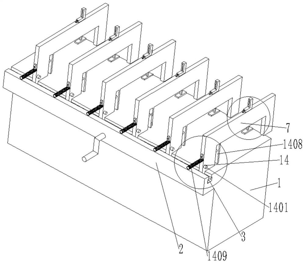
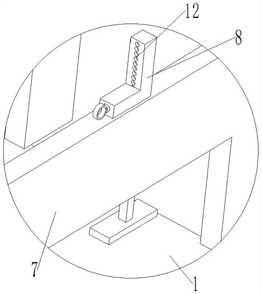
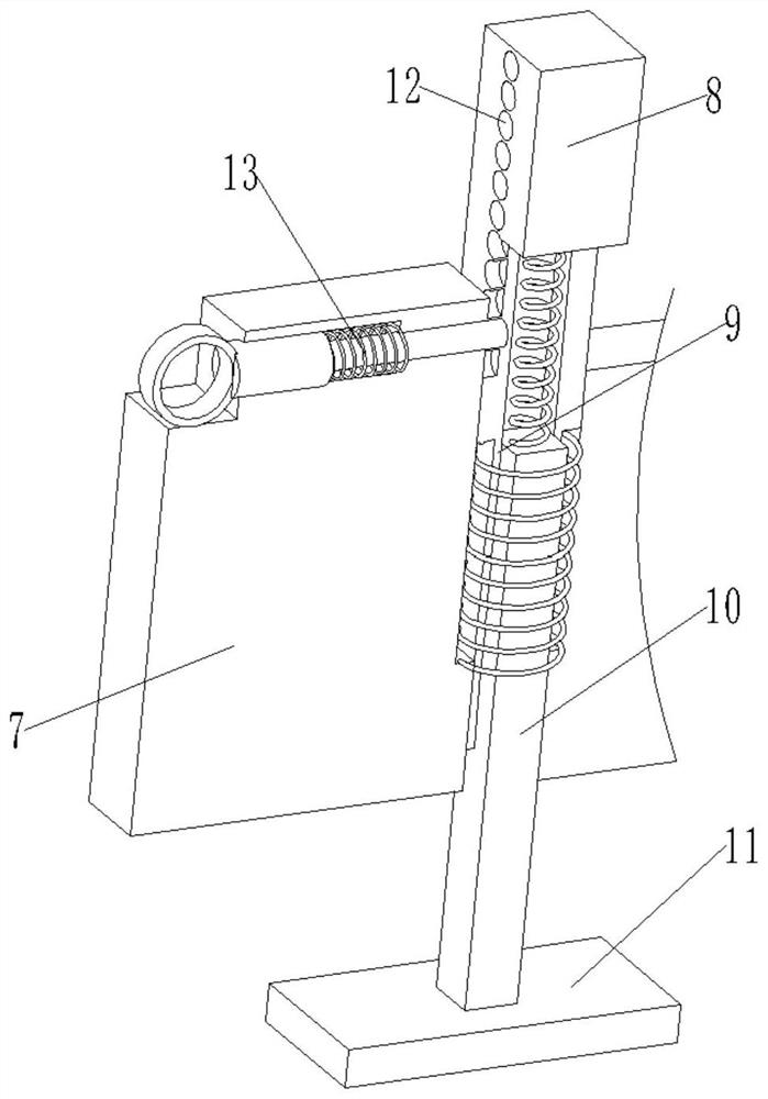
[0027] see figure see Figure 1 to Figure 7 , the present invention provides a technical solution: a positioning mechanism for cutting and processing aluminum profiles, the present invention includes a workbench 1, a placement body 2, a positioning bracket 7 and an auxiliary positioning mechanism 14;

[0028] One side of the workbench 1 is integrally formed with a placement body 2, and the placement body 2 is movably connected with a movable rack 3, and one side of the movable rack 3 is meshed and connected with a gear 4, and the gear 4 is arranged at one end of the handle , the crank handle is set through the placement body 2, and the other side of th...


PUM


Abstract

The invention discloses a positioning mechanism for aluminum profile cutting machining. When the positioning mechanism is used for cutting aluminum profiles, an arranged positioning bracket is firstlyused for primarily positioning the aluminum profiles, and when equal-section cutting positions of the aluminum profiles are determined, the upper sides of the aluminum profiles are pressed through anarranged first positioning pressing plate, so that positioning in the vertical direction is achieved; and then one side of each aluminum profile is pressed and positioned through a second positioningpressing plate arranged in an auxiliary positioning mechanism, and a transverse positioning requirement of the aluminum profiles is met, so that the positioning accuracy, firmness and stability of the aluminum profiles during cutting work are improved, the cutting work of the aluminum profiles can be carried out more smoothly, the cutting quality of the aluminum profiles is guaranteed, the actualrequirements of production work are guaranteed, the production work quality is improved, and the economic benefits of the production work are guaranteed.

Description

technical field [0001] The invention relates to the technical field of aluminum profile processing equipment, in particular to a positioning mechanism for cutting and processing aluminum profiles. Background technique [0002] Aluminum profiles are aluminum materials with different cross-sectional shapes obtained by hot melting and extrusion of aluminum rods; the production process of aluminum profiles mainly includes three processes of melting, extrusion and coloring; among them, coloring mainly includes: oxidation, electrophoresis Coating, fluorocarbon spraying, powder coating, wood grain transfer printing and other processes; in recent years, China's aluminum processing industry has closely combined the needs of the market and scientific development, so that traditional aluminum processing materials have gradually completed the transformation into modern aluminum processing materials Therefore, the variety of aluminum processing materials in China has undergone tremendous...

Claims


Application Information

Patent Timeline
Patent Type & Authority Applications(China)
IPC IPC(8): B23D79/00B23Q3/06
CPCB23D79/00B23Q3/06
Inventor 胡勇涛
Owner 辽宁永壮铝业集团有限公司
Why Eureka
Try Eureka