
Knife switch contact maintenance tool

A technology for overhauling tools and contacts, which is applied to cleaning methods and appliances, switchgear, electrical components, etc., and can solve problems such as easy heating of contacts, personal threats to operators, and small working surfaces

Inactive Publication Date: 2020-10-30
广西电网有限责任公司梧州供电局
View PDF6 Cites 0 Cited by
  • Summary
  • Abstract
  • Description
  • Claims
  • Application Information

AI Technical Summary

Problems solved by technology

The contact finger of the contact finger switch is the place that needs the most frequent inspection and maintenance, because the contact finger is the place that is most prone to heat and has the most serious safety hazard
However, due to the special structure of the contact finger switch, if you do not use special tools, the maintenance of the contact finger is very time-consuming and laborious.
[0003] The existing tools for maintaining the contact fingers, in the process of use, due to the special position of the head and tail of the knife switch contact, the working surface is small, and two or more people are required to clean the contact fingers under the condition of a small working surface; the operation Personnel cannot use special tools to break off the contact fingers, they need to use both hands to open the contact fingers, but the contacts of the contact fingers are sharp, so not only the cleaning of the contact fingers is not thorough enough, but also poses a threat to the operator

Method used


Image

  • Knife switch contact maintenance tool

Examples


Embodiment Construction

[0029] The following will clearly and completely describe the technical solutions in the embodiments of the present invention with reference to the accompanying drawings in the embodiments of the present invention. Obviously, the described embodiments are only some, not all, embodiments of the present invention. Based on the embodiments of the present invention, all other embodiments obtained by persons of ordinary skill in the art without creative efforts fall within the protection scope of the present invention.

[0030] It should be noted that when an element is considered to be "connected" to another element, it may be directly connected to the other element or there may be an intervening element at the same time. When an element is said to be "disposed on" another element, it can be directly disposed on the other element or intervening elements may also be present.

[0031] Unless otherwise defined, all technical and scientific terms used herein have the same meaning as c...


PUM


Abstract

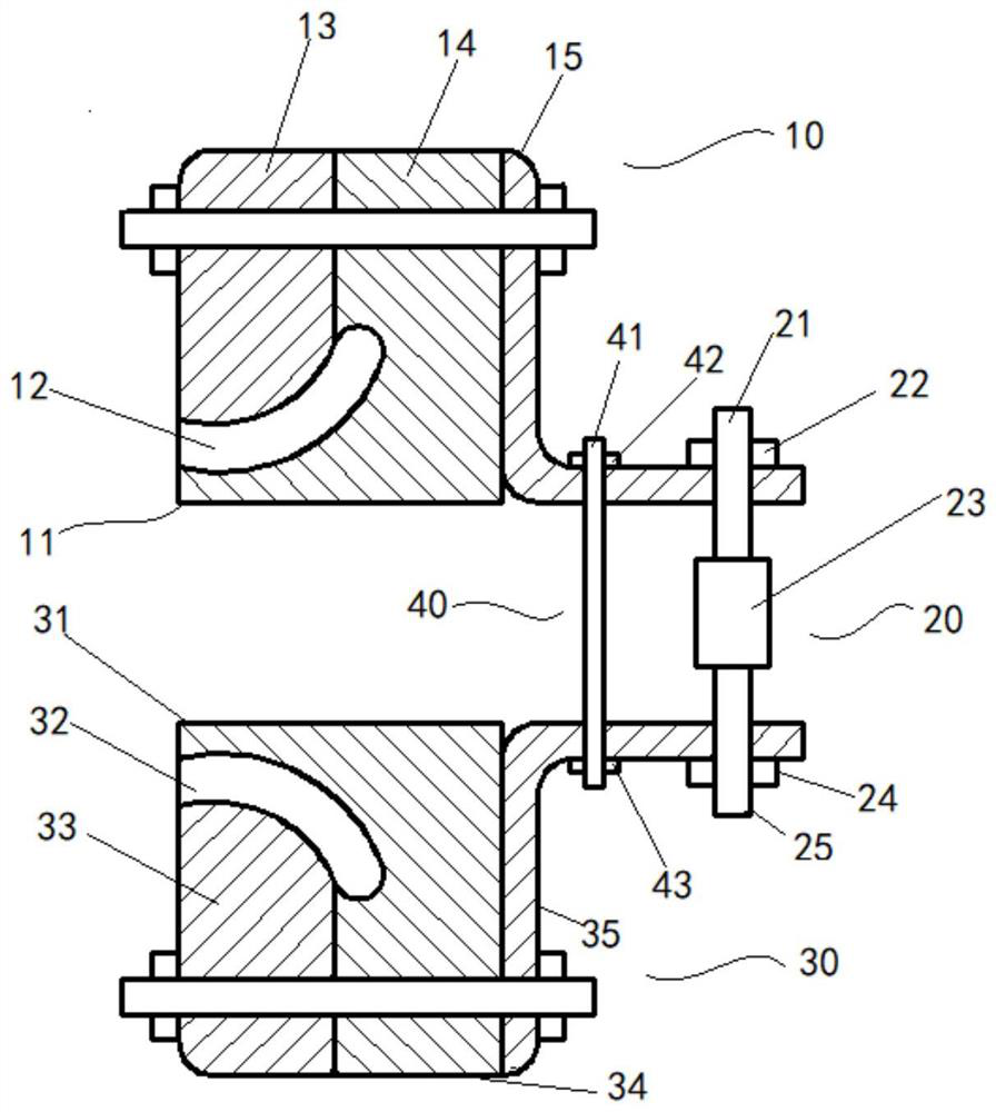
The invention discloses a knife switch contact maintenance tool which comprises a first clamping block assembly, a second clamping block assembly and an adjusting assembly. A first contact finger groove is formed in the front end face of the first clamping block assembly, a second contact finger groove is formed in the front end face of the second clamping block assembly, and the two ends of the adjusting assembly are connected to the rear end of the first clamping block assembly and the rear end of the second clamping block assembly respectively. The distance between the rear end of the firstclamping block assembly and the rear end of the second clamping block assembly is adjusted based on the adjusting assembly. By arranging the first contact finger groove and the second contact fingergroove, the device can be matched with a knife switch contact and does not damage the knife switch contact. The adjusting assembly is set, the distance between the first clamping block assembly and the second clamping block assembly can be adjusted and fixed by operating the adjusting assembly, an operator can concentrate on cleaning of the knife switch contact better, and the purpose of single-person operation is achieved on the premise that the personal safety of the operator is guaranteed.

Description

technical field [0001] The invention relates to the field of knife switch finger cleaning equipment, in particular to a knife switch contact maintenance tool. Background technique [0002] Although there are many types of electric switch switches at present, the finger-type switch accounts for the vast majority of the total in actual use. The contact finger of the contact finger switch is the place that needs the most frequent inspection and maintenance, because the contact finger is the place that is most prone to heat and has the most serious safety hazard. However, due to the special structure of the finger switch, if no special tools are used, the maintenance of the finger is very time-consuming and laborious. [0003] The existing tools for maintaining the contact fingers, in the process of use, due to the special position of the head and tail of the knife switch contact, the working surface is small, and two or more people are required to clean the contact fingers und...

Claims


Application Information

Patent Timeline
IPC IPC(8): H02B3/00B08B13/00
CPCH02B3/00B08B13/00
Inventor 黄敬侠覃飞莲李波
Owner 广西电网有限责任公司梧州供电局
Learn More