Welded joint fatigue life prediction method considering residual stress evolution
A technology for fatigue life prediction and residual stress, which is applied in the direction of prediction, application of repeated force/pulsation force to test material strength, and measurement devices, etc. It can solve problems such as waste of resources, lack of theoretical support, and redistribution of residual stress to avoid high cost, realize scientific prediction, and facilitate engineering application
Pending Publication Date: 2020-10-30
CHINA UNIV OF PETROLEUM (EAST CHINA)
View PDF0 Cites 11 Cited by
- Summary
- Abstract
- Description
- Claims
- Application Information
AI Technical Summary
Problems solved by technology
[0005] Among them, the method based on the S-N curve lacks the necessary theoretical support on the one hand, and adopts an overly conservative safety factor, which easily leads to waste of resources. It needs to rely on a large number of fatigue tests, and the cost is high; the fatigue life prediction method based on fracture mechanics is mainly developed from the perspective of fatigue crack growth, which cannot cover the initiation behavior of fatigue cracks, and in most actual engineering requirements, fatigue crack initiation is not considered. Allowed; although the method based on continuum damage mechanics considers the initiation behavior of fatigue cracks, the implementation process is relatively complicated, the model parameters are numerous, the operator needs to have a strong mechanical foundation, and the analysis method of damage accumulation week by week makes the calculation process Lengthy, difficult to popularize and apply in engineering
[0006] At the same time, when the welding residual stress is superimposed on the external cyclic load, it will cause obvious plastic deformation of the component, resulting in the redistribution of residual stress
Therefore, it is inaccurate to ignore the welding residual stress and its redistribution evolution in the fatigue strength safety assessment of welded joints
Method used
View moreImage
Smart ImageViewing Examples
Examples
Embodiment
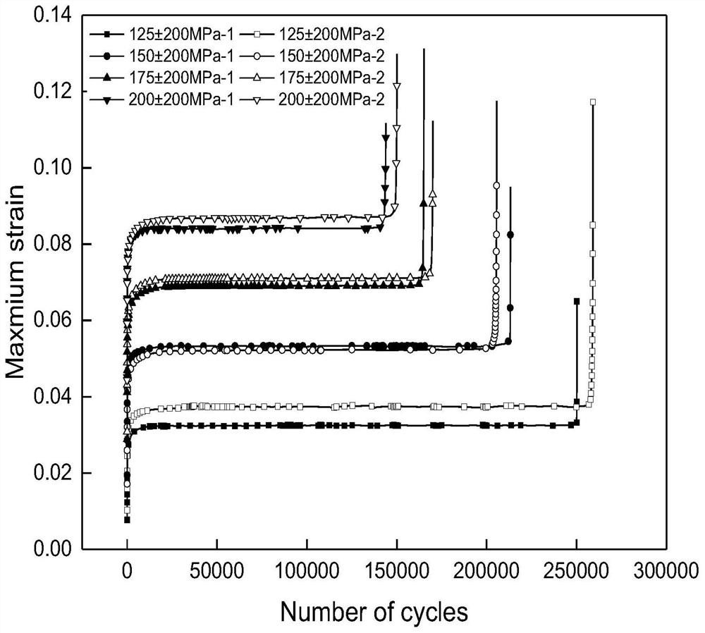
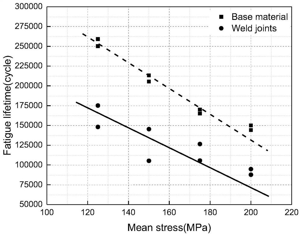
[0128] Taking 316L stainless steel welded joints as the research object, the fatigue life prediction is carried out considering the evolution of residual stress. The specific implementation methods are as follows.
Login to View More PUM
 Abstract
The invention discloses a welded joint fatigue life prediction method considering residual stress evolution. The method comprises the following steps: carrying out a cyclic load fatigue test on base metal; substituting into a parent metal fatigue prediction model considering the average stress, and fitting to obtain material parameters; adopting a sequential coupling method to perform thermal simulation on the weld joint of the welding joint, and determining a welding state residual stress field in the welding process; establishing a cyclic constitutive model based on the stress-strain data ofthe parent metal; simulating a redistribution behavior of the residual stress under a cyclic load, and simulating a maximum steady-state tensile residual stress value [sigma]<re-max>; and correctingthe maximum stress value [sigma]<max> to be the sum of the maximum stress value [sigma]<max0> and the maximum steady-state tensile residual stress value [sigma]<re-max> when the residual stress is notconsidered, and establishing a welded joint fatigue life prediction model considering residual stress evolution. According to the method, the fatigue test is combined with finite element calculation,and the welded joint fatigue life prediction model considering residual stress evolution is established, so that the fatigue life of the welded joint is scientifically predicted.
Description
technical field [0001] The invention belongs to the technical field of fatigue life prediction of welded joints, and in particular relates to a method for predicting the fatigue life of welded joints considering the evolution of residual stress. Background technique [0002] Modern industrial equipment tends to develop in the direction of high output, high parameters and high efficiency. The production process is becoming more and more complex and the production conditions are becoming more and more harsh. The threat of cyclic loading due to factors such as pressure fluctuations. Fatigue cracks are easily generated at structural geometrically discontinuous parts or where there are initial defects, which can lead to major safety accidents such as leakage and explosion, seriously affecting the long-term stable and reliable operation of equipment. [0003] Welding technology has been widely used in the manufacturing process of large-scale and complex engineering structures due...
Claims
Login to View More Application Information
Patent Timeline
 IPC IPC(8): G06Q10/04G06F30/20G06F30/23G01N3/32G06F119/14G06F119/04
CPCG06Q10/04G06F30/20G06F30/23G01N3/32G06F2119/14G06F2119/04G01N2203/0005G01N2203/0073G01N2203/0075
Inventor 蒋文春解学方王天娇张显程涂善东
Owner CHINA UNIV OF PETROLEUM (EAST CHINA)
Features
- Generate Ideas
- Intellectual Property
- Life Sciences
- Materials
- Tech Scout
- Unparalleled Data Quality
- Higher Quality Content
- 60% Fewer Hallucinations
Learn More Browse by: Latest US Patents, China's latest patents, Technical Efficacy Thesaurus, Application Domain, Technology Topic, Popular Technical Reports.
© 2025 PatSnap. All rights reserved.Legal|Privacy policy|Modern Slavery Act Transparency Statement|Sitemap|About US| Contact US: help@patsnap.com


