
Ultra-wideband chirped tilted fiber grating inscribing device, inscribing method and laser system

A tilted fiber grating, ultra-broadband technology, applied in cladding fibers, optical waveguides, light guides, optics, etc., can solve problems such as adverse system effects and insufficient suppression of SRS effects, and achieve the effect of flexible adjustment

Pending Publication Date: 2020-10-30
NAT UNIV OF DEFENSE TECH
View PDF6 Cites 7 Cited by
  • Summary
  • Abstract
  • Description
  • Claims
  • Application Information

AI Technical Summary

Problems solved by technology

However, the bandwidth of chirped tilted fiber gratings reported so far is only on the order of 12nm, which is not enough to suppress the SRS effect, and because of the Bragg resonance reflection of the tilted fiber grating itself, it will have an adverse effect on the normal operation of the system.

Method used


Image

  • Ultra-wideband chirped tilted fiber grating inscribing device, inscribing method and laser system
  • Ultra-wideband chirped tilted fiber grating inscribing device, inscribing method and laser system
  • Ultra-wideband chirped tilted fiber grating inscribing device, inscribing method and laser system

Examples


Embodiment 1

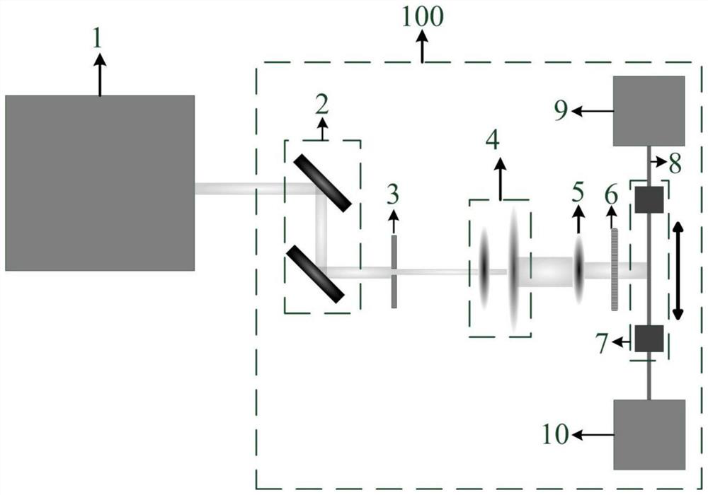
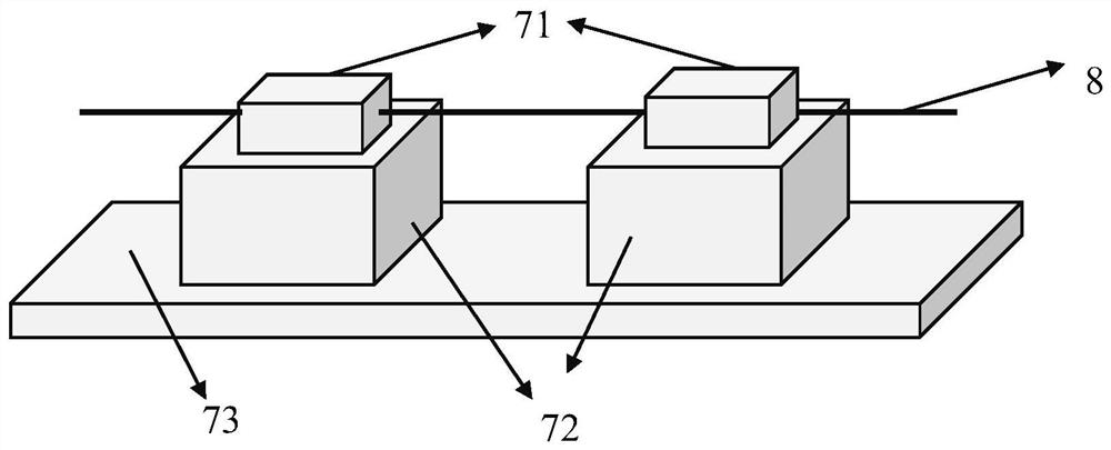
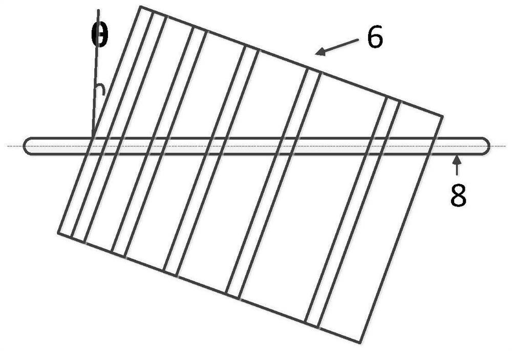
[0057] refer to figure 1 , an ultra-broadband chirped tilted fiber grating writing device, including an optical table 100 and a 248nm excimer laser 1 arranged on the optical table 100, a plane mirror group 2, a diaphragm 3, a beam expander lens group 4, and a focusing cylindrical lens 5. Chirped phase mask 6 and optical fiber operation mobile platform 7 . The phase mask directly determines the period and chirp rate of the written broadband chirped tilted fiber grating. Ultra-bandwidth is realized by the length, tilt angle and chirp rate of the grating. The length of the grating is more than 10cm and the tilt angle is 8° Above, the chirp rate is 1nm / cm.

[0058] The transmission path of the output laser of the 248nm excimer laser 1 is successively provided with a plane reflector group 2, an aperture 3, a beam expander lens group 4, a focusing cylindrical lens 5 and a chirped phase mask 6, from the focusing cylindrical lens 5 The focused outgoing beam hits the center of the gr...

Embodiment 2

[0066] Utilizing the ultra-wideband chirped tilted fiber grating writing device provided in Embodiment 1, this embodiment provides a method for writing ultra-wideband chirped tilted fiber gratings, including the following steps:

[0067] (1) Set the parameters of the excimer laser, including the repetition frequency and voltage of the excimer laser: set the moving distance and moving speed of the optical fiber operation mobile platform; set the tilt angle of the ultra-broadband chirped tilted fiber grating, and the corresponding rotating phase mask is perpendicular to The angle of rotation in the vertical plane of the beam incidence direction is introduced to introduce a tilt angle in the beam path.

[0068] (2) Cut an optical fiber with a suitable length, coat the area where the ultra-broadband chirped tilted fiber grating is to be written with a chemical stripper, wipe it with alcohol, and install the optical fiber on the optical fiber operation mobile platform; connect one e...

Embodiment 4

[0075] Figure 6 It is a schematic structural diagram of embodiment 3; in this embodiment, it is a forward-pumped fiber laser oscillator. A laser system includes a pumping LD light source 101, a pumping beam combiner 102, a high reflection grating 103, a doped optical fiber 104, and a low reflection grating 105. The long period fiber grating 106 is arranged before the low reflection grating 105 in the cavity of the fiber laser oscillator.

[0076] There are multiple pumping LD light sources 101 , and the output pigtails of each pumping LD light source 101 are connected to each pumping arm of the pumping beam combiner 2 . For common fiber laser oscillators, the wavelength of the pump source can be selected as 976nm or 915nm, and the output power is on the order of hundreds of watts. In actual use, the parameters of the pump LD light source 101 , the selected wavelength, the output power, the number used, etc. vary according to requirements, and there is no special requirement...


PUM

PropertyMeasurementUnit
lengthaaaaaaaaaa

Abstract

The invention discloses an ultra-wideband chirped tilted fiber grating inscribing device, an inscribing method and a laser system. The ultra-wideband chirped tilted fiber grating inscribing device comprises an excimer laser, a plane mirror group, a diaphragm, a beam expanding lens group, a focusing column lens, a chirp phase mask plate and an optical fiber operation mobile platform; the plane mirror group, the diaphragm, the beam expanding lens group, the focusing column lens and the chirp phase mask plate are sequentially arranged on a transmission path of laser output by the excimer laser, and a light beam focused and emitted from the focusing column lens vertically irradiates the center of a gate region of the chirp phase mask plate. An optical fiber is installed on the optical fiber operation moving platform and is parallel to the chirp phase mask plate, laser emitted from the chirp phase mask plate vertically enters the optical fiber, and meanwhile, inscribing of the ultra-wideband chirp tilted fiber grating is realized by controlling the optical fiber operation moving platform. The ultra-wideband chirped tilted fiber grating is simple and convenient to manufacture, parameterscan be flexibly adjusted, Raman random laser cannot be excited in a high-power fiber laser system, and the application range of the ultra-wideband chirped tilted fiber grating is greatly expanded.

Description

technical field [0001] The invention relates to the technical field of fiber grating writing and application, in particular to an ultra-broadband chirped tilted fiber grating writing device, writing method and laser system. Background technique [0002] Fiber lasers have the advantages of high efficiency, good beam quality, small size, maintenance-free, low operating cost, high beam quality, long operating life, easy modulation, compact structure, etc., and are widely used in military, industrial and other fields. With the improvement of LD brightness and the advent of double-clad fibers, the output power of fiber lasers has been greatly increased. However, stimulated Raman scattering (SRS) is a key factor that limits the further increase of fiber laser power. The Raman scattered light generated by the SRS effect in the fiber laser is bidirectionally transmitted. On the one hand, the forward transmitted Raman scattered light will compete with the signal light, resulting in ...

Claims


Application Information

Patent Timeline
Patent Type & Authority Applications(China)
IPC IPC(8): G02B6/02
CPCG02B6/02138
Inventor 王泽锋王蒙李宏业田鑫赵晓帆饶斌裕胡琪浩奚小明陈子伦潘志勇王小林许晓军陈金宝
Owner NAT UNIV OF DEFENSE TECH
Learn More