Eureka AIR delivers breakthrough ideas for toughest innovation challenges, trusted by R&D personnel around the world.

Electric leakage alarm monitoring device

A monitoring device and transmission line technology, applied in the field of electric power, can solve the problems of inability to accurately detect the leakage of transmission lines, reduction of working current, personal injury, etc., and achieve the effects of reducing property loss, reducing leakage and increasing loss.

Active Publication Date: 2020-10-30
海南电网有限责任公司琼中供电局
View PDF11 Cites 4 Cited by
  • Summary
  • Abstract
  • Description
  • Claims
  • Application Information

AI Technical Summary

Problems solved by technology

[0003] In the actual application of power transmission lines, if there is a leakage in a certain position, especially when the leakage is relatively large, on the one hand, it will lead to a reduction in the working current transmitted, and the loss will On the other hand, the electricity leaked from the transmission line will also cause electric shock to nearby pedestrians, causing personal injury
However, based on the above problems, the current device cannot accurately detect the leakage of the transmission line and give an alarm in time

Method used


Image

  • Electric leakage alarm monitoring device
  • Electric leakage alarm monitoring device
  • Electric leakage alarm monitoring device

Examples


Embodiment Construction

[0035] This part will describe the specific embodiment of the present invention in detail, and the preferred embodiment of the present invention is shown in the accompanying drawings. Each technical feature and overall technical solution of the invention, but it should not be understood as a limitation on the protection scope of the present invention.

[0036] In the description of the present invention, it should be understood that the orientation descriptions, such as "up", "down", "front", "rear", "left", "right" and other indications are based on The orientations or positional relationships shown in the drawings are only for the convenience of describing the present invention and simplifying the description, and do not indicate or imply that the referred device or element must have a specific orientation, be constructed and operated in a specific orientation, and therefore cannot be understood as Limitations on the Invention.

[0037] In the description of the present inv...


PUM


Abstract

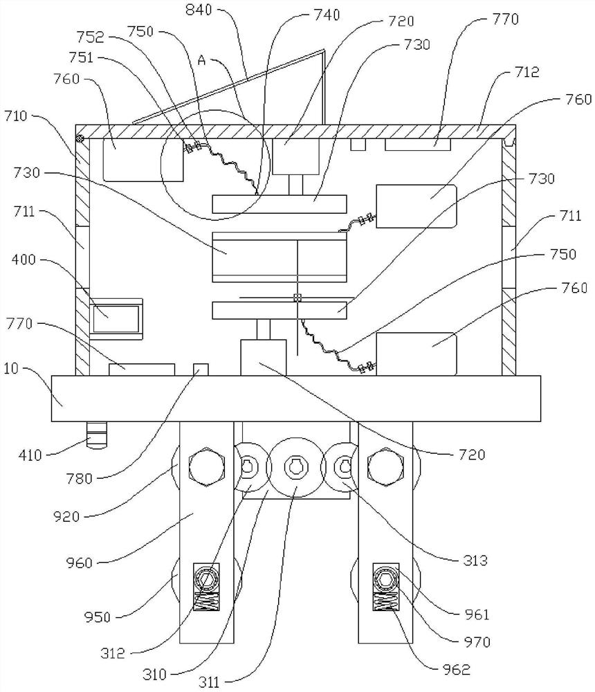
The invention provides an electric leakage alarm monitoring device which is used for detecting a power transmission line and comprises a moving mechanism and a gluing mechanism. Guide rods are arranged on the front and rear sides of the power transmission line respectively; a moving mechanism driven by a motor is arranged on the two guide rods, the motor is electrically connected with a controller, and the controller is electrically connected with an alarm; a second current sensor and a first current sensor electrically connected with the controller are respectively arranged at the left and right ends of the power transmission line; the gluing mechanism comprises a box body arranged on the moving mechanism, and first through holes are formed in the front side wall and the rear side wall inthe box body respectively; first telescopic rods and electric leakage detection sensors used for detecting electric leakage positions are arranged on the upper inner side wall, the lower inner side wall, the front inner side wall and the rear inner side wall in the box body correspondingly, and first arc plates are arranged on the first telescopic rods; and the first arc plates are provided withglue spraying heads, the glue spraying heads are communicated with a liquid storage bottle through a conveying pipe with a first pump, and a heater is arranged in the box body. When the difference value of the current magnitudes detected by the first current sensor and the second current sensor is greater than a set value, the alarm gives an alarm under control.

Description

technical field [0001] The invention relates to the field of electric power technology, in particular to a leakage alarm monitoring device for detecting transmission lines. Background technique [0002] In recent years, transmission lines have been widely used in urban power construction, substations and power plants, and are also an important part of urban power supply, substations and power plants, so the safe operation of transmission lines has become an object of widespread concern. [0003] In the practical application of transmission lines, if there is a leakage in a certain position, especially when the leakage is relatively large, on the one hand, it will reduce the working current and increase the loss. On the other hand, the leakage of electricity from the transmission line will also affect Pedestrians nearby were shocked by the electric shock, causing personal injury. However, based on the above-mentioned problems, the current device cannot accurately detect the ...

Claims


Application Information

Patent Timeline
IPC IPC(8): G01R31/52G08B21/18
CPCG01R31/52G08B21/185
Inventor 张昌庆陈垠锟曾飞顾育滨姚佳高曼梁钰
Owner 海南电网有限责任公司琼中供电局
Why Eureka
Eureka Blog
Learn More