
Detection device of electrical automation equipment

An electrical automation and testing device technology, applied in measuring devices, measuring device housings, components of electrical measuring instruments, etc., can solve problems such as risks in the quality of electrical automation equipment, inaccurate testing, and increased disassembly difficulty, to avoid Secondary dust return, ensure detection performance, strengthen the effect of connection

Pending Publication Date: 2020-10-30
宿州学院
View PDF21 Cites 0 Cited by
  • Summary
  • Abstract
  • Description
  • Claims
  • Application Information

AI Technical Summary

Problems solved by technology

[0003] In an electrical automation processing factory, since fine suspended particles such as dust are produced during processing and fill the entire factory, the detection probe will inevitably be contaminated with certain suspended particles such as dust. After a period of time, the probe will not be able to detect accurately enough. , thereby affecting its detection performance, which in turn leads to risks in the quality of electrical automation equipment
[0004] The detection devices of the existing electrical automation equipment all use the detection instrument to be installed above the transmission device, so that the probe of the detection instrument is directly facing the electrical automation equipment on the transmission device for detection. If the detection probe needs to be cleaned, the probe needs to be cleaned. However, since the detection probe is directly above the transmission device, the ladder needs to be placed on one side of the transmission device during disassembly, and the person standing on the ladder leans at a large angle to remove it, which makes disassembly more difficult, thus Difficult to clean

Method used


Image

  • Detection device of electrical automation equipment
  • Detection device of electrical automation equipment
  • Detection device of electrical automation equipment

Examples


Embodiment Construction

[0037] A specific embodiment of the present invention will be described in detail below in conjunction with the accompanying drawings, but it should be understood that the protection scope of the present invention is not limited by the specific embodiment.

[0038] In describing the present invention, it should be understood that the terms "center", "longitudinal", "transverse", "length", "width", "thickness", "upper", "lower", "front", " Rear", "Left", "Right", "Vertical", "Horizontal", "Top", "Bottom", "Inner", "Outer", "Axial", "Radial", "Circumferential" The orientation or positional relationship indicated by etc. is based on the orientation or positional relationship shown in the drawings, and is only for the convenience of describing the technical solution of the present invention and simplifying the description, rather than indicating or implying that the referred device or element must have a specific orientation, Constructed and operative in a particular orientation a...


PUM


Abstract

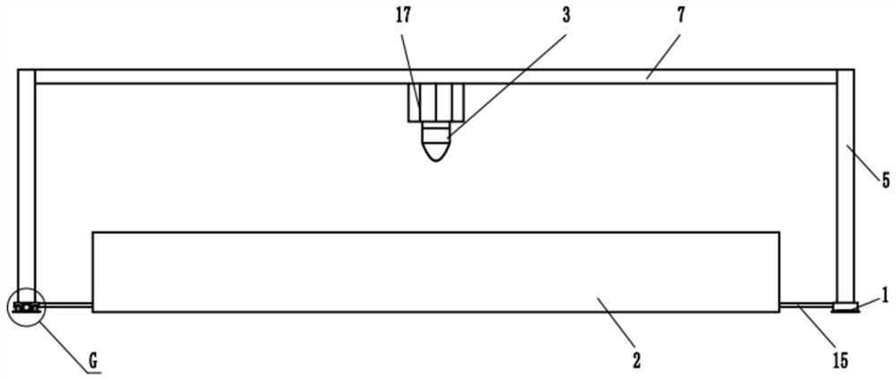
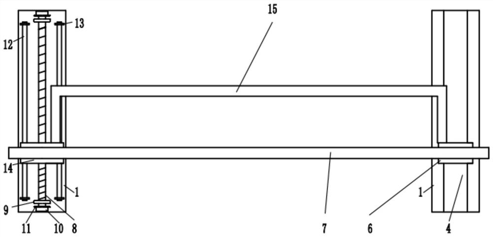
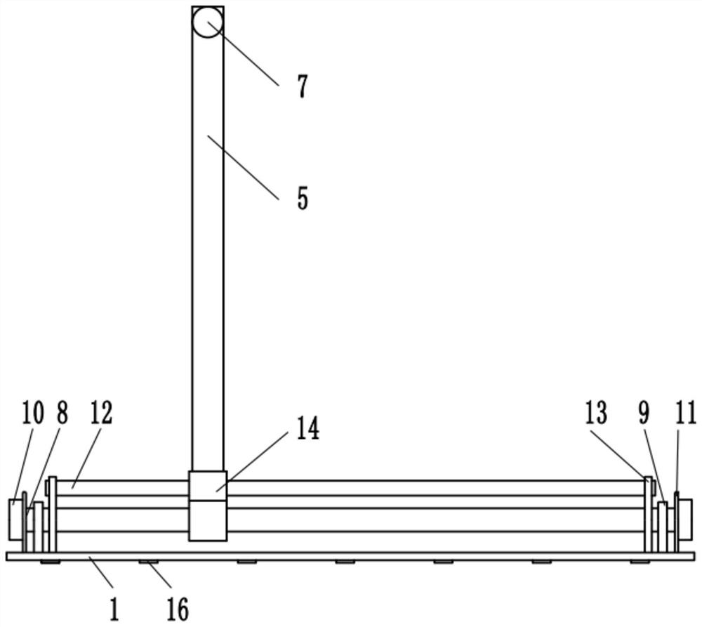
The invention relates to the technical field of detection devices. The invention discloses a detection device of electrical automation equipment. The device comprises a base, a sliding device, a sliding rail, two stand columns, a cross beam, a threaded rod, a motor, two limiting rods and a moving block. The base is fixed on the ground, the two ends of the threaded rod are connected with the base through first supporting bases. A motor output shaft is in shaft connection with one end of the threaded rod; the two limiting rods are fixedly connected with the base; the moving block is in threadedconnection with the periphery of the threaded rod; the two limiting rods penetrate through the positions, close to the two sides, of the moving block respectively and are in sliding connection with the moving block, the sliding rail is fixedly connected to the base on the other side, the lower ends of the two stand columns are fixedly connected with the moving block and the locking sliding block respectively, the two ends of the beam are fixedly connected with the upper portions of the two stand columns respectively, and the detection probe is arranged on the beam and right faces the conveyingdevice. The detection device can be moved to the rear side or the front side of the conveying device, a worker can clean the detection probe conveniently, and the detection performance of the detection probe is guaranteed.

Description

technical field [0001] The invention relates to the technical field of detection devices, in particular to a detection device for electrical automation equipment. Background technique [0002] With the rapid development of social economy, electrical automation technology has been widely applied to various industries in society, which greatly improves production efficiency and liberates productivity. It plays an important role in improving product quality and maintaining core competitiveness. Electrical automation control equipment plays a vital role in the development of electrical automation. In the production process of electrical automation equipment, it is necessary to use testing devices to perform performance testing on electrical automation equipment. [0003] In an electrical automation processing factory, since fine suspended particles such as dust are produced during processing and fill the entire factory, the detection probe will inevitably be contaminated with ce...

Claims


Application Information

Patent Timeline
IPC IPC(8): G01R31/00G01R1/04G01R1/02
CPCG01R31/00G01R1/0408G01R1/02
Inventor 郭凯周莹冯浩郭焕银韩君柏植
Owner 宿州学院
Learn More