Oil pressure drive system and gate valve

A drive system and oil pressure technology, applied in the direction of sliding valves, fluid pressure actuators, valve details, etc., can solve the problems of high power consumption of servo motors, improve operational reliability, reduce power consumption, and improve operational reliability Effect

Active Publication Date: 2020-10-30
ULVAC INC
View PDF9 Cites 0 Cited by
  • Summary
  • Abstract
  • Description
  • Claims
  • Application Information

AI Technical Summary

Problems solved by technology

[0019] In addition, although the influence of the cogging torque on the normally closed operation can be reduced by using a servo motor, in this case, there is a problem that it is not advisable because the power consumption of the servo motor is large.

Method used


Image

  • Oil pressure drive system and gate valve
  • Oil pressure drive system and gate valve
  • Oil pressure drive system and gate valve

Examples


Embodiment

[0525] Next, examples of the present invention will be described.

[0526] Here, performance analysis will be described as a specific example of the hydraulic drive system of the present invention.

[0527]

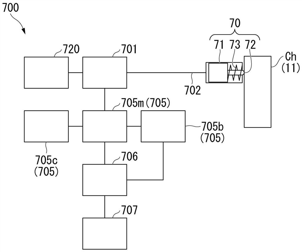
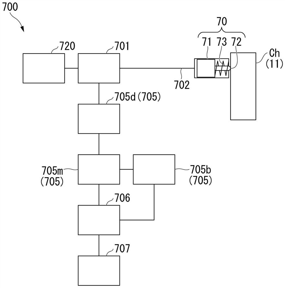
[0528] First, the type of the motor 705m, the structure of the counter-rotation countermeasure required for this, the electric power required at this time, and the life of the combined structure are analyzed.

[0529] Here, as the motor 705m, a brushed DC motor, a coreless brushless DC motor, and a stepping motor are analyzed. Also, analyze the need for cogging torque countermeasures for these motors.

[0530] As the structure of the counter-rotation countermeasure, the solenoid valve, the field clutch 705d and the field brake 705b for preventing the reverse rotation of the drive system at the time of oil pressure reverse flow are analyzed. In addition, it is analyzed whether the regenerative current processing unit 705c is necessary.

[0531] In addition, the power ...


PUM


Abstract

The invention discloses an oil pressure drive system and a gate valve. The oil pressure drive system is an oil pressure drive system that can expand and contract so as to press an object in a chamberin a vacuum atmosphere. The oil pressure drive system has a vacuum actuator and an oil pressure driving unit. The oil pressure driving unit includes an oil pressure generating unit, a driving unit fordriving the oil pressure generating unit, and a power source for supplying power to the driving unit. A telescopic rod can be driven by working oil pressure supplied from the oil pressure driving unit to the fixed section. The driving unit is provided with a reversal response portion, and when the telescopic rod moves in a direction away from the object by the force of an oil pressure urging member, the reversal response portion responds to the reverse state of the motor.

Description

technical field [0001] The present invention relates to an oil pressure drive system and a gate valve, in particular to a technique suitable for use in an oil pressure drive system and a pendulum gate valve using the oil pressure drive system. Pressure driven and rebound vacuum actuator. Background technique [0002] A telescopic actuator that presses an object in a vacuum atmosphere chamber is provided in a vacuum apparatus or the like. As such a telescopic actuator, there is known a configuration in which a drive unit is arranged outside the chamber in a vacuum atmosphere to drive the telescopic unit in the chamber from the viewpoint of preventing contamination in the chamber. [0003] For example, the telescopic actuator has an electromagnetic drive type, a pneumatic drive type, or a hydraulic drive type. [0004] On the other hand, the inventors of the present invention filed a patent application (Patent Document 1) related to a pendulum gate valve having a hydraulical...

Claims


Application Information

Patent Timeline
Patent Type & Authority Applications(China)
IPC IPC(8): F16K3/02F16K31/122F04B37/14
CPCF16K3/0254F16K31/122F04B37/14F15B13/042F15B13/044F16K51/02F16K31/12F16K3/30H02K7/102H02K29/00H02K26/00F15B2211/89
Inventor 德平真之介井上英晃柴山浩司和出拓也古濑晴邦猿渡治郎铎木干也和田慎一照井敬晶迫田圣也石田智也
Owner ULVAC INC
Why Eureka
Try Eureka