
Aero-engine fan unit and aero-engine

An aero-engine and fan technology, which is applied in the direction of machines/engines, liquid fuel engines, and parts of pumping devices for elastic fluids, etc., can solve the problems of increasing engine weight, high positioning accuracy of holes on the installation side, and flow channel plates. Small installation space and other issues, to achieve the effect of improving safety and reliability, easy assembly and maintenance, and accurate installation and positioning

Active Publication Date: 2022-02-22
AECC COMML AIRCRAFT ENGINE CO LTD
View PDF6 Cites 0 Cited by
  • Summary
  • Abstract
  • Description
  • Claims
  • Application Information

AI Technical Summary

Problems solved by technology

[0004] The above structure mainly has the following defects: the structure of this installation method is complex, the positioning accuracy of the holes on the installation side is high, and the manufacturing process is difficult; due to the small installation space of the flow channel plate, the assembly is difficult, and the maintenance and repair difficulty increases
Moreover, both the bottom of the flow channel plate and the outer wall of the fan disk need to increase the installation edge structure, and accessories such as bolts are also required for installation, which will increase the weight of the related installation structure of the flow channel plate, thereby increasing the weight of the engine and reducing the load on the engine
In addition, during the operation of the engine, there are still gas leaks at the connection, which reduces the efficiency of the engine

Method used


Image

  • Aero-engine fan unit and aero-engine
  • Aero-engine fan unit and aero-engine
  • Aero-engine fan unit and aero-engine

Examples


Embodiment Construction

[0043] The present invention will be described in detail below. In the following paragraphs, different aspects of the embodiments are defined in more detail. Aspects so defined may be combined with any other aspect or aspects unless specifically stated otherwise. In particular, any feature considered to be preferred or advantageous may be combined with one or more other features which are considered to be preferred or advantageous.

[0044] Terms such as "first" and "second" appearing in the present invention are only for convenience of description, to distinguish different components with the same name, and do not indicate a sequence or a primary and secondary relationship.

[0045] In the description of the present invention, orientations or positional relationships indicated by "upper", "lower", "top", "bottom", "front", "rear", "inner" and "outer" are used based on the attached The orientation or positional relationship shown in the figure is only for the convenience of ...


PUM


Abstract

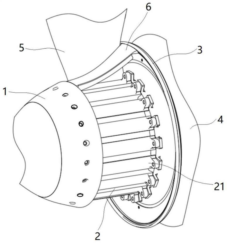
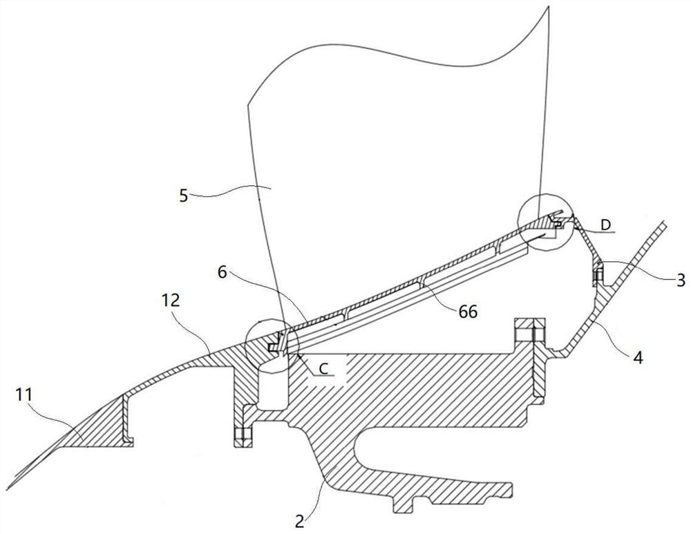
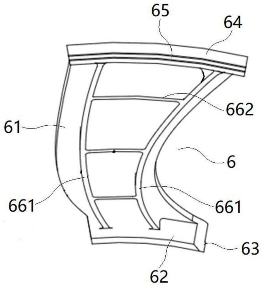
The invention relates to an aero-engine fan device and an aero-engine, wherein the fan device comprises: an air intake cone (1); a sealing ring (3); a fan disk (2), which is axially arranged on the air intake cone (1) and between the sealing ring (3); a plurality of blades (5) are arranged at intervals along the circumferential direction on the outer wall of the fan disc (2); and a plurality of flow channel plates (6), and the flow channel plates (6) are arranged on Between the roots of two adjacent blades (5); wherein, the end face of the air intake cone (1) facing the fan disk (2) is provided with a plurality of first grooves (121) at intervals in the circumferential direction, and the sealing ring (3 ) towards the end surface of the fan disk (2) is provided with a plurality of second grooves (31) at intervals in the circumferential direction, and the two ends of the flow channel plate (6) along the axial direction are respectively connected with the first grooves (121) and the second grooves Groove (31) fitting. The fan device has a simple structure, is convenient to process, and can reduce weight; moreover, it can reduce the installation difficulty of the runner plate, and is easy to assemble and maintain.

Description

technical field [0001] The invention relates to the technical field of aero-engines, in particular to an aero-engine fan device and an aero-engine. Background technique [0002] The fan device of an axial-flow aero-engine is used to realize air intake. Its structure is as follows: along the axial direction of the engine, it includes an intake cone, a fan disc, a sealing ring and a drum, and a plurality of blades are arranged at intervals in the circumferential direction of the fan disc. A flow channel plate is arranged between adjacent blades, and the flow channel plate, the intake cone and the sealing ring form the flow channel of the engine intake section. [0003] In the related technology known to the inventor, the flow channel plate adopts the following installation structure: the bottom of the flow channel plate is provided with an installation edge extending in the axial direction, and correspondingly, the fan disc is also provided with an installation edge correspond...

Claims


Application Information

Patent Timeline
Patent Type & Authority Patents(China)
IPC IPC(8): F04D19/00F04D29/54F04D29/16F04D29/64
CPCF04D19/002F04D29/541F04D29/164F04D29/646
Inventor 喻思杨凌元马天宇
Owner AECC COMML AIRCRAFT ENGINE CO LTD
Learn More