
Electroplating equipment capable of reducing edge effect and working method of electroplating equipment

An electroplating equipment and edge effect technology, applied in the electrolysis process, electrolysis components, cells, etc., can solve problems affecting the quality of the coating, and achieve the effects of avoiding coating peeling, increasing turbulence, and precise displacement control

Inactive Publication Date: 2020-10-30
孙国栋
View PDF0 Cites 0 Cited by
  • Summary
  • Abstract
  • Description
  • Claims
  • Application Information

AI Technical Summary

Problems solved by technology

[0005] The purpose of the present invention is to solve the disadvantages that most of the rack plating equipment in the prior art is a welded integrated structure, which easily leads to the occurrence of edge effects and affects the quality of the coating, and proposes a kind of electroplating equipment that can reduce the edge effect and its working method

Method used


Image

  • Electroplating equipment capable of reducing edge effect and working method of electroplating equipment
  • Electroplating equipment capable of reducing edge effect and working method of electroplating equipment
  • Electroplating equipment capable of reducing edge effect and working method of electroplating equipment

Examples


Embodiment 1

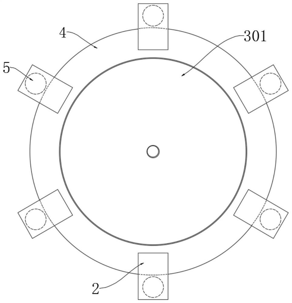
[0029] refer to Figure 1-5 , a working method of electroplating equipment that can reduce edge effects, the specific use method is as follows:

[0030] S1. Clamping workpieces: fix the workpieces on multiple hangers 5 respectively, so that the workpieces are distributed as evenly as possible, and uneven distribution of workpieces may lead to inconsistent thickness of the coating;

[0031] S2. Replenishing electrolyte: observe the liquid level of the electrolyte in the plating tank 1, replenish the electrolyte to make it reach the standard height, then turn on the control switch, and observe whether the equipment can work normally;

[0032] S3, electroplating: start to electroplate the workpiece, remove the workpiece after the electroplating is completed, and prepare for electroplating of the next batch of workpieces;

[0033] The above-mentioned electroplating equipment that can reduce the edge effect also involves a kind of electroplating equipment during use, including a p...

Embodiment 2

[0042] refer to Image 6 The difference between this embodiment and Embodiment 1 is that: the upper surface of the positioning plate 4 is provided with an annular groove, and a plurality of sliding seats 9 are slidably arranged in the annular groove, and the sliding seats 9 can rotate freely along the annular groove, and each fixed Seats 2 are mounted on the upper ends of corresponding sliding seats 9, and solenoids 10 are arranged in each sliding seat 9, and electrorheological fluid is filled in the annular groove.

[0043] During specific work, when the sizes of the workpieces are different, if the arrangement of the fixed hangers 5 is still followed, the distance between the larger workpieces and the adjacent workpieces will be relatively close, and even the workpieces will overlap each other, which will affect the quality of the coating. , so the current can be passed into the solenoid 10 through the control device, so that two adjacent solenoids 10 repel or attract each o...


PUM


Abstract

The invention discloses a working method of electroplating equipment capable of reducing an edge effect. The working method comprises the following steps of S1, clamping a workpiece; S2, supplementingelectrolyte; and S3, electroplating. The electroplating equipment comprises a plating tank and a driving motor; a positioning disc is rotationally installed in the plating tank through a bearing, a plurality of hangers are circumferentially connected to the positioning disc through a fixed seat, an output shaft of the driving motor is fixedly connected with a rotating shaft through a coupler, andthe rotating shaft is coaxial with the positioning disc and fixedly connected with the positioning disc through a connecting disc; and the bottom end of the rotating shaft is fixedly connected with atransmission mechanism, and the transmission mechanism is in interference fit with an annular sealing box. The edge effect during electroplating can be effectively reduced, the bubble adhesion on thesurface of a workpiece is reduced, the plating quality is improved, and in addition, position distribution of the hangers can be quickly changed according to workpiece specification, and the platingthickness is more uniform.

Description

technical field [0001] The invention relates to the technical field of electroplating, in particular to an electroplating device capable of reducing edge effects and a working method thereof. Background technique [0002] In the process of metal workpiece processing, electroplating is an extremely important link. A complete coating can prevent metal oxidation and improve the corrosion resistance of the workpiece. Some special coatings can also improve the wear resistance and conductivity of the workpiece. Electroplating It is also commonly used in the processing of handicrafts, and the luster and feel of handicrafts can be changed through plating. [0003] Electroplating includes rack plating, barrel plating, continuous plating, etc. Common rack plating equipment is mostly a welded integrated structure. During the electroplating process, the position of the rack is fixed, and the distance between adjacent racks is also fixed, so it is easy to The edge effect is produced, re...

Claims


Application Information

Patent Timeline
Patent Type & Authority Applications(China)
IPC IPC(8): C25D21/10C25D21/04C25D21/12
CPCC25D21/04C25D21/10C25D21/12
Inventor 孙国栋
Owner 孙国栋
Learn More