Intelligent stamping mechanism capable of achieving automatic feeding and discharging

A technology of automatic loading and unloading and stamping mechanism, which is applied to presses, manufacturing tools, etc., and can solve problems such as potential safety hazards, increased production costs, and limited work efficiency

Active Publication Date: 2020-10-30
深圳市领拓实业有限公司
View PDF14 Cites 0 Cited by
  • Summary
  • Abstract
  • Description
  • Claims
  • Application Information

AI Technical Summary

Problems solved by technology

[0002] Sheet metal stamping is very common in the mechanical production process. Conventional sheet metal stamping adopts a structural design in which the movable mold and the fixed mold cooperate with each other. When loading and unloading, staff are required to operate. This working mode not only The work efficiency is limited, and the work intensity is relatively high, and there are serious safety hazards;
[0003] In order to solve the above problems, those skilled in the art have designed an automatic loading and unloading device suitable for stamping machines. However, the structure of this automatic loading and unloading device is relatively complicated, and in order to ensure the automatic working effect, more electronic components and control components are required. The production cost is greatly increased, and at the same time, it is more difficult in the later use and maintenance, and the maintenance cost is higher

Method used


Image

  • Intelligent stamping mechanism capable of achieving automatic feeding and discharging
  • Intelligent stamping mechanism capable of achieving automatic feeding and discharging
  • Intelligent stamping mechanism capable of achieving automatic feeding and discharging

Examples


Embodiment Construction

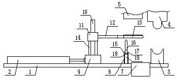
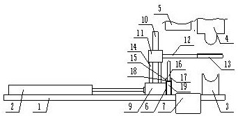
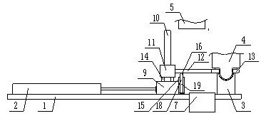
[0031] The present invention is specifically described below in conjunction with accompanying drawing, as Figure 1-7 shown;

[0032] The invention point of the present application is that the return rod 6 is fixedly installed on the base between the cylinder and the fixed mold, and the finished product box 7 is installed on the base between the described return rod and the fixed die, and the return rod and the cylinder The base between is provided with guide rail 8, and described guide rail is parallel with the connecting line between return bar and cylinder telescopic rod, and sliding seat 9 is installed on described guide rail, and described sliding seat is fixed with the telescopic rod of cylinder by flange Connect and slide along the guide rail driven by the telescopic rod;

[0033] The inventive point of the present application is also that a column 10 is provided on the sliding seat, a slide block 11 is installed on the column, the slide block slides up and down along ...


PUM


Abstract

The invention discloses an intelligent stamping mechanism capable of achieving automatic feeding and discharging. The intelligent stamping mechanism comprises a base, wherein an air cylinder is fixedly installed at one end of the base, a fixed die is fixedly installed at the other end of the base, a movable die is arranged above the fixed die, a discharging guide groove frame is arranged above thebase, a workpiece withdrawing rod is fixedly installed at the position, between the air cylinder and the fixed die, of the base, a finished product box is installed on the position, between the workpiece withdrawing rod and the fixed die, of the base, a guide rail is arranged on the position, between the workpiece withdrawing rod and the air cylinder, of the base, the guide rail is parallel to aconnecting line between the workpiece withdrawing rod and a telescopic rod of the air cylinder, a sliding seat is installed on the guide rail, and the sliding seat is fixedly connected with the telescopic rod of the air cylinder through a flange and is driven by the telescopic rod to slide along the guide rail. The mechanism has the beneficial effects that the automatic workpiece feeding and withdrawing functions are achieved through the simple mechanical structure design, and the production cost and the maintenance cost are effectively reduced while the working efficiency is guaranteed.

Description

technical field [0001] The invention relates to the technical field of stamping mechanical structure improvement, in particular to an intelligent stamping mechanism capable of automatic loading and unloading. Background technique [0002] Sheet metal stamping is very common in the mechanical production process. Conventional sheet metal stamping adopts a structural design in which the movable mold and the fixed mold cooperate with each other. When loading and unloading, staff are required to operate. This working mode not only The work efficiency is limited, and the work intensity is relatively high, and there are serious safety hazards; [0003] In order to solve the above problems, those skilled in the art have designed an automatic loading and unloading device suitable for stamping machines. However, the structure of this automatic loading and unloading device is relatively complicated, and in order to ensure the automatic working effect, more electronic components and con...

Claims


Application Information

Patent Timeline
IPC IPC(8): B30B15/30B30B15/32
CPCB30B15/30B30B15/32
Inventor 姚敦卫
Owner 深圳市领拓实业有限公司
Why Eureka
Try Eureka