Intelligent wrist equipment system of industrial robot and operation method thereof

A technology of industrial robots and robots, which is applied in the direction of manipulators, manufacturing tools, chucks, etc., can solve the problems of multi-processing accumulation errors, large space utilization, and compact installation layout.

Pending Publication Date: 2020-10-30
广西利拓智能科技股份有限公司
View PDF0 Cites 3 Cited by
  • Summary
  • Abstract
  • Description
  • Claims
  • Application Information

AI Technical Summary

Problems solved by technology

[0008] 1. The overall layout of the external module of the existing industrial robot smart wrist equipment system is fixed, and the installation position is relatively harsh for the actual working environment, which cannot meet the needs of the actual working environment
[0009] 2. If the external modules such as the bus module, electrical connection module, welding module and water-gas module are too large in size, positional interference may also occur due to the problem of installation angle
[0010] 3. Because the installation position and angle of the side of the main body are fixed, the installation layout of the bus module, electrical connection module, water and air module, welding module and other external modules cannot be relatively compact, and the space to be used is relatively large
For the machining of the side installation position, multiple clamping is required to complete, to a certain extent, more cumulative processing errors will be generated; in addition, the side installation position has very high requirements for machining, and the overall quality requirements of the machining personnel required It is also very high. If the machining environment is slightly insufficient, the overall quality of the machining personnel will often affect whether the position tolerance of the installation position of the side external module is within the allowable tolerance range.
[0012] 5. There is no detection and counting module, so it is impossible to detect whether the steel ball is actually inflated in place, so there is a safety risk of being virtual in place; at the same time, it is impossible to detect the number of times the steel ball is not inflated, so it cannot provide technical support for later structural improvement

Method used


Image

  • Intelligent wrist equipment system of industrial robot and operation method thereof
  • Intelligent wrist equipment system of industrial robot and operation method thereof
  • Intelligent wrist equipment system of industrial robot and operation method thereof

Examples


Embodiment Construction

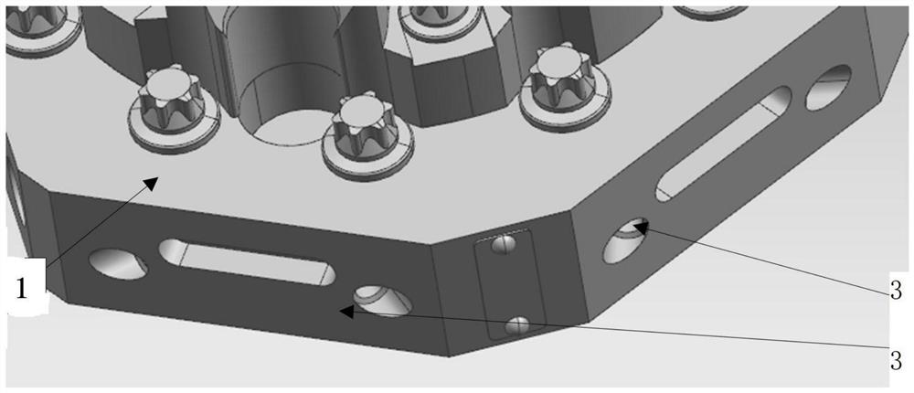
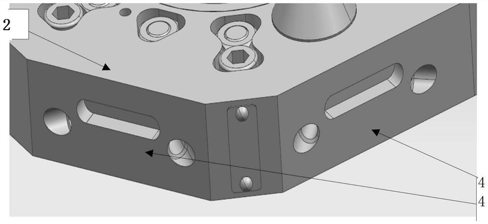
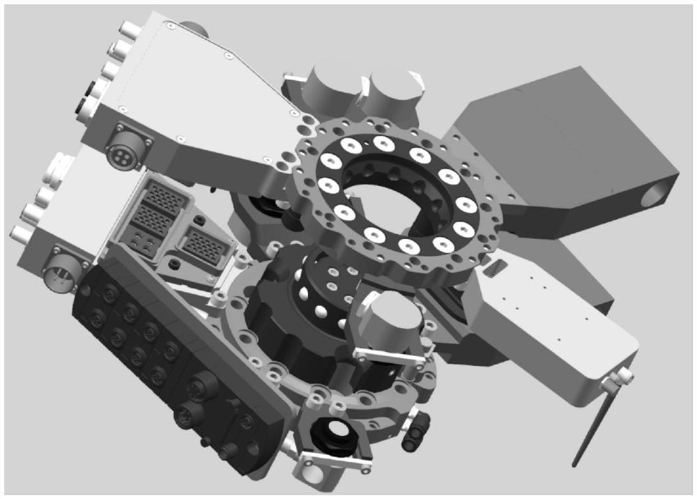
[0062] see image 3 as well as Figure 12 , the industrial robot intelligent wrist equipment system of the first embodiment includes: a robot side and a tool side, the robot side is fixed at the end flange of the robot, the tool side is locked on the robot side, and the tool sides are respectively fixed to realize various For tools with different functions, the robot side and the tool side form a one-to-many relationship. Through the macroscopic movement and microscopic capture movement of the robot side, different tools are taken out or replaced from the tool rack to realize the system function.

[0063] see Figure 4 , 6, 8 and Figure 9 , the robot side includes: robot side flange main body 11, robot side BK module 12, robot side electrical connection structure module 13, robot side welding module 14, robot side water and air module 15, robot side locking end 16, steel ball 17, robot side Side positioning hole 18, solenoid valve 19, pressure sensor 20, in-position sensor...


PUM


Abstract

The invention provides an intelligent wrist equipment system of an industrial robot. The intelligent wrist equipment system comprises a robot side and a tool side, wherein the robot side comprises a robot side flange main body, a robot side BK module, a robot side electrical connecting structure module, a robot side welding module, a robot side water vapor module, a robot side locking end, a steelball, a robot side positioning hole, a solenoid valve, a pressure sensor, a locking compression spring, a sealed cylinder body, a piston, a magnetic ring, a sealing ring, a tapered groove lock core,a robot side in-position sensor, a robot side module positioning hole, a module positioning sleeve, a robot side piston magnetic switch sensor and a robot side electrical connecting module guide sleeve. The tool side comprises a tool side flange form main body, a tool side positioning pin, a tool side curved locking ring, a tool side electrical connecting structure module, a water vapor module, awelding module, a tool side detection and counting module, a tool side curved surface locking end steel ball locking matching groove, a tool side module positioning hole and a tool side electrical connecting module guide pin. The invention also provides a corresponding operation method.

Description

technical field [0001] The invention belongs to the technical field of intelligent manufacturing, and in particular relates to an industrial robot intelligent wrist equipment system (auto tools change, ATC for short) and an operation method thereof. Background technique [0002] In the context of Industry 4.0, industrial robots play a pivotal role in the field of manufacturing. Traditional industrial robots are designed based on scheduled tasks, and their fixed structures show great limitations. Most robots are in automation Only one operation can be completed in the production process. In the actual production process, a product needs to go through multiple complex processes, and the robot at each station is responsible for a single job. The enterprise needs to configure multiple robots to complete the entire process. Such automation The production line requires a large number of robots, takes up a lot of work space, and greatly increases the manufacturing cost of the enter...

Claims


Application Information

Patent Timeline
IPC IPC(8): B25J15/04B25J19/00
CPCB25J15/04B25J19/00
Inventor 张健尧永春龚兴元何宗平韦学谦
Owner 广西利拓智能科技股份有限公司
Why Eureka
Try Eureka