
Assembly line sand core mold batch transfer table

A technology of transfer table and sand core mold, which is applied in the direction of mold handling equipment, metal processing equipment, casting equipment, etc., can solve the problems of floating sand falling, no self-cleaning function, floating sand accumulation, etc., to achieve enhanced falling , easy to slide, avoid the effect of accumulation

Inactive Publication Date: 2020-10-30
ANHUI QUANCHAI TIANHE MACHINERY
View PDF6 Cites 0 Cited by
  • Summary
  • Abstract
  • Description
  • Claims
  • Application Information

AI Technical Summary

Problems solved by technology

[0002] Mold casting is a widely used form of casting. As the name suggests, it is to use sand to make molds. Sand mold casting needs to put the finished part model or wooden model (pattern) in the sand, then fill the sand around the pattern, and open the box. After the pattern is taken out, the sand forms the casting mold. After the sand core mold is in the manufacturing place, it needs to be transferred. During the transfer process, the sand core mold is prone to floating sand falling off, but the traditional transfer table is mostly a flat transfer table. , without self-cleaning function, it is easy to cause floating sand accumulation, which affects the placement and transfer of sand core molds. Therefore, we propose a batch transfer platform for sand core molds in an assembly line to solve the above problems

Method used


Image

  • Assembly line sand core mold batch transfer table
  • Assembly line sand core mold batch transfer table
  • Assembly line sand core mold batch transfer table

Examples


Embodiment Construction

[0019] The following will clearly and completely describe the technical solutions in the embodiments of the present invention with reference to the accompanying drawings in the embodiments of the present invention. Obviously, the described embodiments are only some, not all, embodiments of the present invention. Based on the embodiments of the present invention, all other embodiments obtained by persons of ordinary skill in the art without making creative efforts belong to the protection scope of the present invention.

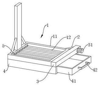
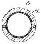
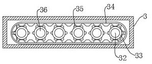
[0020] see Figure 1-3 , the present invention provides a technical solution: a batch transfer platform for assembly line sand core molds, including a transfer platform 1, the transfer platform 1 includes a return frame 11, the inner wall of the return frame 11 is rotatably connected to several weighing rods 12, and the return The side wall of the frame 11 is fixedly provided with a rectangular box 3, the side wall of one end of the rectangular box 31 is fixed...


PUM


Abstract

The invention discloses an assembly line sand core mold batch transfer table. The assembly line sand core mold batch transfer table comprises a transfer table body; the transfer table body comprises aconcentric-square-shaped frame, a plurality of weighing rods are rotationally connected with the inner wall of the concentric-square-shaped frame, and a rectangular box is fixedly arranged on the side wall of the concentric-square-shaped frame; a driving motor is installed on the side wall of one end of the rectangular box, the rotating end of the driving motor penetrates through the side wall ofthe rectangular box to be fixedly connected with a driving shaft, and the outer wall of the end, located in the rectangular box, of the driving shaft is sleeved with a driving gear; and the driving gear is engaged with a crawler belt, a rack on the crawler belt is engaged with a plurality of driven gears, inner rings of the driven gears are fixedly connected with driven shafts, one ends of the driven shafts are rotationally connected with the inner wall of the rectangular box, and the other ends of the driven shafts are fixedly connected with one ends of weighing rods. According to the device, floating sand is prevented from being accumulated on the transfer table body, the rotating end of the driving motor drives the driving shaft, the driving gear, the crawler belt, the driven gears, the driven shafts and the weighing rods to rotate, falling of the floating sand on the weighing rods is further enhanced, and the self-cleaning effect of the transfer table body is achieved.

Description

technical field [0001] The invention relates to the technical field of a transfer platform for sand core molds, in particular to a batch transfer platform for sand core molds on an assembly line. Background technique [0002] Mold casting is a widely used form of casting. As the name suggests, it is to use sand to make molds. Sand mold casting needs to put the finished part model or wooden model (pattern) in the sand, then fill the sand around the pattern, and open the box. After the pattern is taken out, the sand forms the casting mold. After the sand core mold is in the manufacturing place, it needs to be transferred. During the transfer process, the sand core mold is prone to floating sand falling off, but the traditional transfer table is mostly a flat transfer table. , without self-cleaning function, it is easy to cause floating sand to accumulate, which affects the placement and transfer of sand core molds. Therefore, we propose a batch transfer platform for assembly l...

Claims


Application Information

Patent Timeline
Patent Type & Authority Applications(China)
IPC IPC(8): B22D33/02
CPCB22D33/02
Inventor 梁守友
Owner ANHUI QUANCHAI TIANHE MACHINERY
Learn More