
Steel coil feeding and centering method

A steel coil and coiling technology, applied in metal rolling, manufacturing tools, metal processing equipment, etc., can solve problems such as difficulty in realizing automatic coiling, increasing labor intensity and labor cost of workers, and operation accuracy being greatly affected by personnel quality.

Inactive Publication Date: 2020-10-30
WEIER AUTOMATION CO LTD TANGSHAN IRON & STEELGRP +1
View PDF8 Cites 4 Cited by
  • Summary
  • Abstract
  • Description
  • Claims
  • Application Information

AI Technical Summary

Problems solved by technology

[0002] At the entrance of the cold-rolling production line, when the steel coil is loaded onto the uncoiler mandrel, the center line in the width direction of the steel coil and the center line of the rolling mill (that is, the center line of the mandrel) must coincide, so that the strip steel will not deviate during uncoiling. The traditional method is Manual winding, because the operator is operating on the operating side, facing the steel coil, whether the steel coil is installed in the middle of the mandrel needs to be observed from the side of the mandrel, so two people are required to cooperate when coiling, and the operation accuracy is greatly affected by the quality of the personnel , uncontrollable, increasing the labor intensity and labor cost of workers, it is difficult to realize automatic winding, which restricts the improvement of production rhythm

Method used


Image

  • Steel coil feeding and centering method
  • Steel coil feeding and centering method
  • Steel coil feeding and centering method

Examples


Embodiment Construction

[0025] The present invention will be described in further detail below in conjunction with the examples.

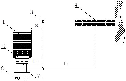
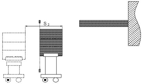
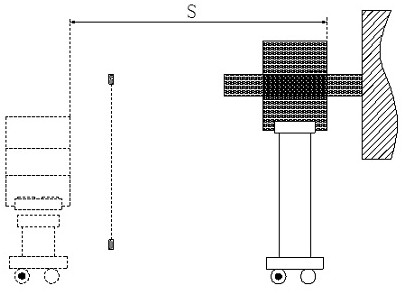
[0026] The invention discloses a coil centering method for steel coils, see Figure 1-Figure 3 , install the saddle 9 of the steel coil 1, the winding trolley 7 and the uncoiler mandrel 4, install the grating 3 between the saddle 9 and the uncoiler mandrel 4, and install the grating for distance measurement on the winding trolley 7 Encoder 8, when the winding trolley 7 is raised to the operating height, it moves towards the direction of the uncoiler mandrel 4, and records the value of the encoder 8 when the steel coil 1 blocks the grating 3, and then the winding trolley 7 continues to move, when the steel coil 1 When the grating 3 is out, record the value of the encoder 8 again, and calculate the deviation ε between the center line of the steel coil 1 width direction and the center line of the saddle 9 width direction when the steel coil 1 is on the saddle 9, by the saddl...


PUM


Abstract

The invention relates to a steel coil feeding and centering method. After a steel coil is lifted from a saddle to the height of a running position by a coil feeding trolley, the steel coil is draggedto move to the direction of an uncoiling machine mandrel to pass through a grating, and according to a formula epsilon= L2-(S1 + S2) / 2, the deviation epsilon between the center line of the saddle andthe center line of the steel coil when the steel coil is placed on the saddle is calculated, S1 is the distance between the edge of the steel coil and the grating, L1 is the distance between the center of the saddle and the center of the of the uncoiling machine mandrel, S2 is the distance traveled by the trolley when the steel coil moves out of the grating, and the distance S required to move forcentering the steel coil and a rolling line is L1-epsilon, that is, S = L1-L2 +(S1 + S2) / 2, and L2 is the distance between the center of the saddle and the grating. The method is simple, and the horizontal moving distance of the coil feeding trolley can be automatically calculated.

Description

technical field [0001] This patent application belongs to the technical field of automatic control of cold rolling, and more specifically relates to a coil centering method for steel coils. Background technique [0002] At the entrance of the cold-rolling production line, when the steel coil is loaded onto the uncoiler mandrel, the center line in the width direction of the steel coil and the center line of the rolling mill (that is, the center line of the mandrel) must coincide, so that the strip steel will not deviate during uncoiling. The traditional method is Manual winding, because the operator is operating on the operating side, facing the steel coil, whether the steel coil is installed in the middle of the mandrel needs to be observed from the side of the mandrel, so two people are required to cooperate when coiling, and the operation accuracy is greatly affected by the quality of the personnel , uncontrollable, increasing the labor intensity and labor cost of workers,...

Claims


Application Information

Patent Timeline
IPC IPC(8): B21B15/00B21C47/24
CPCB21B15/00B21C47/24
Inventor 高亚东韩一杰彭爱辉王学峰唐颖董一鸣吴亚军
Owner WEIER AUTOMATION CO LTD TANGSHAN IRON & STEELGRP
Learn More