Self-cleaning device for medium-efficiency electronic air purification device

A technology of electronic air and purification equipment, applied in the field of air purification in the subway, can solve the problems of strong cleaning expertise, long cleaning time, and great safety, and achieve the effects of reducing labor costs, improving cleaning cleanliness, and best cleaning effect

Pending Publication Date: 2020-10-30
BEIJING JIEYUTONG ENVIRONMENTAL PROTECTION SCI & TECH
View PDF0 Cites 0 Cited by
  • Summary
  • Abstract
  • Description
  • Claims
  • Application Information

AI Technical Summary

Problems solved by technology

[0004] The purpose of the present invention is to provide a self-cleaning device for medium-efficiency electronic air purification equipment to solve the above-mentioned background technology that the current air purification devices in the subway do not have self-cleaning functions, and professionals need to perform manual maintenance on the purification device on a regular basis. In the actual operation of this maintenance method, there are operational difficulties such as large labor expenditure, long cleaning time and strong cleaning expertise, which leads to the problem of low actual operation efficiency of the purification device, and in bad weather conditions, due to the use of high pressure in the air purification device Static electricity is used for dust removal, and the subway environment is mostly fine dust rich in metal powder. Once the dust collection ion box collects dust to a certain extent, an instantaneous arc or short circuit will occur, and then there will be a large potential safety hazard.

Method used


Image

  • Self-cleaning device for medium-efficiency electronic air purification device
  • Self-cleaning device for medium-efficiency electronic air purification device
  • Self-cleaning device for medium-efficiency electronic air purification device

Examples


Embodiment Construction

[0023] The following will clearly and completely describe the technical solutions in the embodiments of the present invention with reference to the accompanying drawings in the embodiments of the present invention. Obviously, the described embodiments are only some, not all, embodiments of the present invention. Based on the embodiments of the present invention, all other embodiments obtained by persons of ordinary skill in the art without making creative efforts belong to the protection scope of the present invention.

[0024] In the description of the present invention, it should be noted that the terms "upper", "lower", "inner", "outer", "front end", "rear end", "both ends", "one end", "another end" The orientation or positional relationship indicated by etc. is based on the orientation or positional relationship shown in the drawings, and is only for the convenience of describing the present invention and simplifying the description, rather than indicating or implying that ...


PUM


Abstract

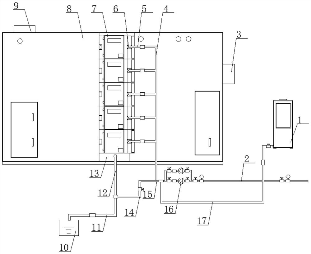
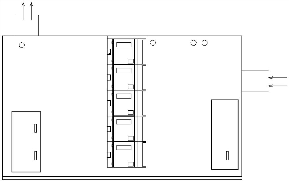
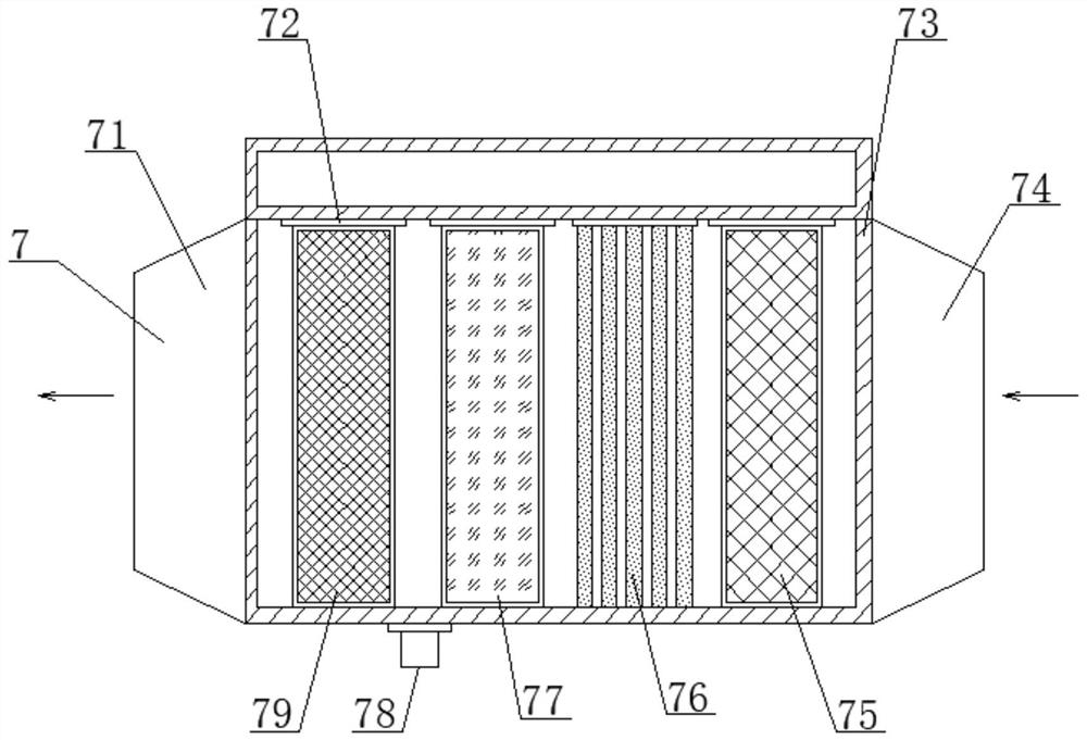
The invention discloses a self-cleaning device for a medium-efficiency electronic air purification device. The self-cleaning device comprises a purification machine body and a liquid medicine pump machine, wherein the right side of the purification machine body is provided with the liquid medicine pump machine, the top end, near the edge of the left side, of the purification body is connected witha purification discharge port in a penetrating mode, the right end, near the middle position, of the purification machine body is connected with a purification inlet in a penetrating mode, the innerside, at the vertical position, of the purification machine body is provided with a purification module, the purification module is equally bolted to the inner side of the purification machine body, the bottom end, close to the bottom side of the purification machine body, of the purification module is provided with a water collecting tank, the water collecting tank is bolted to the inner side ofthe purification machine body through screws, the front end, close to the edge position of the right side, of the purification module is provided with water liquid pipe openings, and the end portionsof each water liquid pipe opening is connected with one end of each cleaning branch pipe. The labor expenditure cost can be greatly reduced, and meanwhile the excellent cleaning effect is obtained.

Description

technical field [0001] The invention belongs to the related technical field of air purification in subways, and in particular relates to a self-cleaning device for medium-efficiency electronic air purification equipment. Background technique [0002] As the main means of transportation in large cities, the subway has become the preferred means of transportation for most people due to its punctuality and convenience. Due to the superposition of outdoor air pollutants and pollutants generated by trains running in the tunnel, the air quality in the subway platform has deteriorated. Therefore, in order to improve the air quality in the subway, most subway projects have used air purification devices. [0003] The existing self-cleaning device technology for air purification equipment has the following problems: At present, the air purification devices in the subway do not have the self-cleaning function, and professionals need to perform manual maintenance on the purification dev...

Claims


Application Information

Patent Timeline
IPC IPC(8): B08B3/04B08B3/08B08B13/00B61D27/00
CPCB08B3/04B08B3/08B08B13/00B61D27/00
Inventor 韩云龙罗贻文葛建新
Owner BEIJING JIEYUTONG ENVIRONMENTAL PROTECTION SCI & TECH
Why Eureka
Try Eureka