
Printed circuit board positioning device based on ratchet wheel positioning principle

A technology for printed circuit boards and positioning devices, which is applied to printed circuits, printed circuit manufacturing, and printed circuit assembly of electrical components, and can solve problems such as inaccurate control of clamping force, economic loss, and damage to circuit boards.

Inactive Publication Date: 2020-10-27
项新华
View PDF0 Cites 5 Cited by
  • Summary
  • Abstract
  • Description
  • Claims
  • Application Information

AI Technical Summary

Problems solved by technology

[0003] During the clamping process of the existing printed circuit board fixture device, the clamping operation is complicated by screws, and the clamping force is not controlled accurately, which is easy to cause damage to the circuit board and cause unnecessary economic losses. The printed circuit board can only be fixed on a plane, and the glue dispenser and welding machine can only glue and weld on the plane, to complete relatively simple glue and welding, and the circuit board needs to be turned over, and the circuit often needs to be disassembled. Re-clamping leads to complex operation and low work efficiency, and the existing circuit board fixture device needs to customize a specific mold for each circuit board to adapt to the fixing of circuit boards of different sizes, thus greatly increasing the cost of the mold , reducing economic benefits

Method used


Image

  • Printed circuit board positioning device based on ratchet wheel positioning principle
  • Printed circuit board positioning device based on ratchet wheel positioning principle
  • Printed circuit board positioning device based on ratchet wheel positioning principle

Examples


Embodiment Construction

[0024] The following will clearly and completely describe the technical solutions in the embodiments of the present invention with reference to the accompanying drawings in the embodiments of the present invention. Obviously, the described embodiments are only some, not all, embodiments of the present invention. Based on the embodiments of the present invention, all other embodiments obtained by persons of ordinary skill in the art without making creative efforts belong to the protection scope of the present invention.

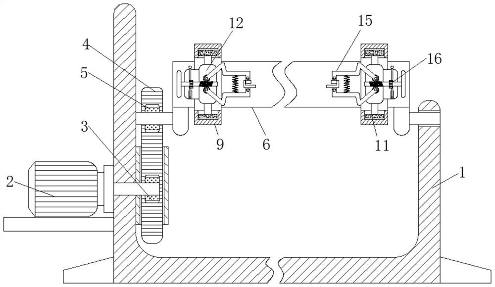
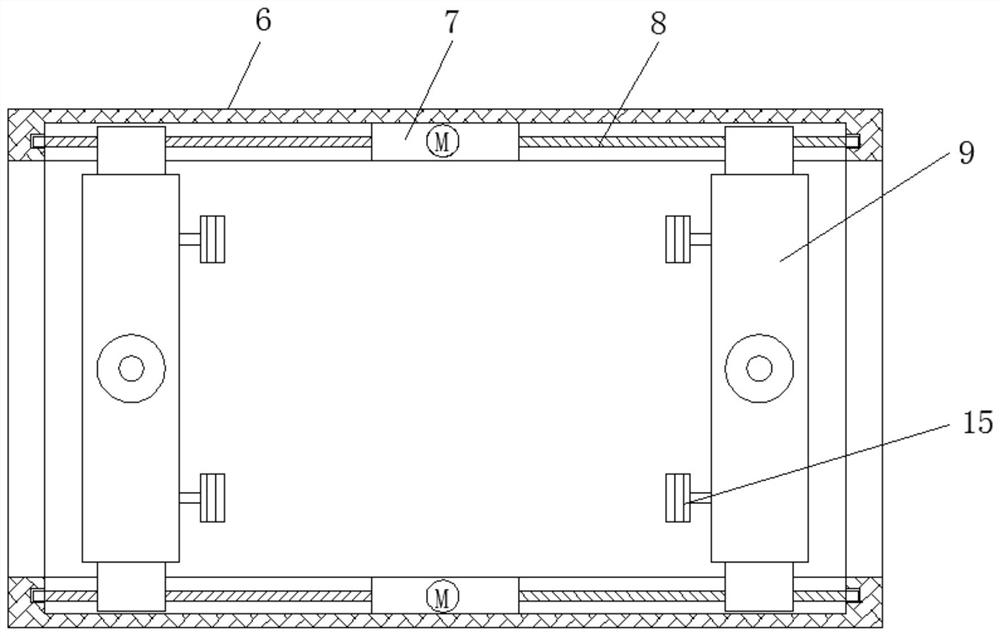
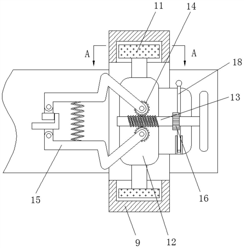
[0025] see Figure 1-5 , a printed circuit board positioning device based on the ratchet positioning principle, including a support frame 1, a turning motor 2, a main gear 3, a turning gear rod 4, a turning gear 5, a fixed frame 6, a moving motor 7, a screw rod 8, and a positioning block 9. Adjusting gear 10, adjusting gear rod 11, slide block 12, threaded rod 13, clamping gear 14, clamping rod 15, positioning ratchet 16, positioning pawl 17, adjusting rod 18,...


PUM


Abstract

The invention relates to the technical field of printed circuits. The invention further discloses a printed circuit board positioning device based on the ratchet wheel positioning principle. The positioning device comprises a supporting frame and the outer portion of the supporting frame is fixedly connected with an overturning motor. A main gear is fixedly connected to the outer part of the overturning motor; the outer portion of the main gear is connected with an overturning toothed bar in an engaged mode. an overturning gear is connected to the outer part of the overturning toothed bar in ameshing manner; a fixing frame is fixedly connected to the outer part of the overturning gear; a moving motor is fixedly connected to the interior of the fixing frame; the overturning motor, a main gear, the overturning toothed bar, the overturning gear and the fixing frame are matched for use; therefore, the effect of conveniently adjusting the angle of the fixing frame is achieved, the printedcircuit substrate can be adjusted to a proper angle, dispensing and welding operation is facilitated, the using effect is effectively improved, overturning operation of the printed circuit board is facilitated, operation is easy, the overturning operation difficulty of the printed circuit board is reduced, time waste is effectively reduced, and the working efficiency is improved.

Description

technical field [0001] The invention relates to the technical field of printed circuits, in particular to a printed circuit board positioning device based on the ratchet positioning principle. Background technique [0002] Circuit printing adopts photoplate making technology, that is, etching the bottom plate of the photographed picture on a copper plate or zinc plate, and using this copper plate or zinc plate for printing has made significant progress compared with traditional circuit boards. Today, all computers and All electronic products use printed circuits. When used, the printed circuit is usually etched on the printed circuit substrate, and all electrical components are connected to the printed circuit substrate by soldering and dispensing on the printed circuit board to make a circuit. When welding and dispensing electrical components, it is usually necessary to clamp and fix the printed circuit board. [0003] During the clamping process of the existing printed ci...

Claims


Application Information

Patent Timeline
IPC IPC(8): H05K3/34
CPCH05K3/34H05K2203/0165H05K2203/15
Inventor 项新华
Owner 项新华
Learn More