
Dual-band dielectric resonator antenna for millimeter wave application

A dielectric resonator, dual-band technology, applied in resonators, antennas, waveguide-type devices, etc., can solve the problem that the antenna cannot achieve millimeter-wave dual-band coverage, and achieve the effect of great practical value

Active Publication Date: 2020-10-27
NANTONG UNIVERSITY
View PDF8 Cites 6 Cited by
  • Summary
  • Abstract
  • Description
  • Claims
  • Application Information

AI Technical Summary

Problems solved by technology

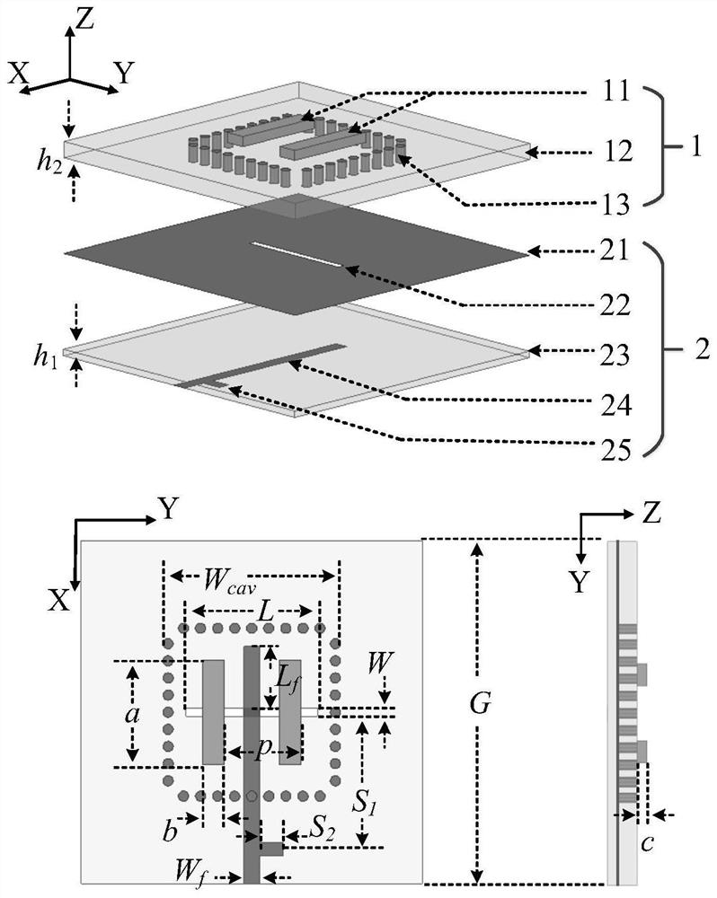
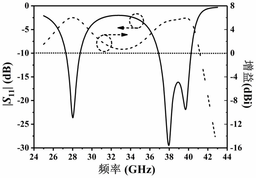
[0004] In order to solve the above problems, the present invention provides a dual-band dielectric resonator antenna for millimeter wave applications, which uses a microstrip line to feed the gap of the stacked dielectric resonator, and solves the problem of high radiation efficiency and low profile structure. The problem that the antenna cannot achieve millimeter-wave dual-band coverage

Method used


Image

  • Dual-band dielectric resonator antenna for millimeter wave application
  • Dual-band dielectric resonator antenna for millimeter wave application
  • Dual-band dielectric resonator antenna for millimeter wave application

Examples


Embodiment Construction

[0023] Specific embodiments of the present invention have been described above. It should be understood that the present invention is not limited to the specific embodiments described above, and those skilled in the art may make various changes or modifications within the scope of the claims, which do not affect the essence of the present invention. It should be noted that the terms "vertical", "horizontal", X-axis, Y-axis, Z-axis and similar expressions used herein are for the purpose of illustration only. Unless otherwise defined, all technical and scientific terms used herein have the same meaning as commonly understood by one of ordinary skill in the technical field of the invention. The terms used herein in the description of the present invention are for the purpose of describing specific embodiments only, and are not intended to limit the present invention.

[0024] like figure 1 As shown, the embodiment of the present invention discloses a dual-band dielectric resona...


PUM

PropertyMeasurementUnit
thicknessaaaaaaaaaa
thicknessaaaaaaaaaa
dielectric lossaaaaaaaaaa

Abstract

The invention discloses a dual-band dielectric resonator antenna for millimeter wave application, and the antenna comprises a laminated dielectric resonator which consists of a high-dielectric-constant dielectric sheet and a low-dielectric-constant second dielectric substrate, and the dielectric sheet is located on the upper surface of the second dielectric substrate; a microstrip feed panel, composed of a metal ground, a first dielectric substrate and a microstrip line. The microstrip feed plate is positioned below the laminated dielectric resonator. The metal ground and the microstrip line are located on the upper and lower opposite surfaces of the first dielectric substrate. One end of the microstrip line extends to the edge of the first dielectric substrate, is connected with the feeder line and feeds the stacked dielectric resonator through the gap, and the gap is formed in the metal ground and is perpendicular to the microstrip line. According to the invention, the microstrip line is used for feeding the laminated dielectric resonator through the gap, two resonance modes are formed, and the problem that the dielectric antenna cannot realize millimeter wave dual-band coverageon the basis of high radiation efficiency and low profile structure is solved.

Description

technical field [0001] The invention belongs to the technical field of antennas, and more specifically relates to a dual-band dielectric resonator antenna for millimeter wave applications. Background technique [0002] The two core requirements in the fifth generation mobile communication technology (5G) are high speed and low power consumption. Millimeter wave technology is a key factor to achieve high data rate wireless communication. In the enhanced mobile broadband scenario, the theoretical peak data rate is even higher than 10GB / S. On the other hand, the dense deployment of base stations and the emergence of terminal equipment with various functions require that 5G must improve energy utilization efficiency. Considering that the practical application of the millimeter wave cellular network and the consumer orientation of the market are highly pursuing the miniaturization and thinning of equipment, in this context, as far as the field of antenna technology is concerned,...

Claims


Application Information

Patent Timeline
Patent Type & Authority Applications(China)
IPC IPC(8): H01Q1/36H01Q1/38H01Q1/48H01Q5/10H01Q13/08H01P7/10
CPCH01Q1/38H01Q1/48H01Q13/08H01P7/10H01Q5/10H01Q1/36Y02D30/70
Inventor 杨汶汶崔伦雪陈建新
Owner NANTONG UNIVERSITY
Learn More