Laser induction strip and induction method

A technology of laser sensing and laser sending and receiving, applied in the field of laser sensing, can solve the problems of small sensing distance, poor blocking and isolation effect of impurity light source, fluctuation of sensing distance, etc.

Pending Publication Date: 2020-10-27
帷幄匠心科技(杭州)有限公司
View PDF18 Cites 1 Cited by
  • Summary
  • Abstract
  • Description
  • Claims
  • Application Information

AI Technical Summary

Problems solved by technology

[0004] Infrared sensing equipment for sensing objects usually includes an infrared emitting device and an infrared receiving device. The infrared emitting device emits infrared rays outward, and the infrared receiving device receives reflected infrared rays. In the prior art, the sensing of corresponding objects usually calculates the infrared rays reflected from the object end Intensity, and set the intensity threshold, if the received infrared reflection light intensity is less than the set threshold value, it can be judged that the item is outside the sensing range, if the received infrared reflection light intensity is greater than the set threshold value, it can be judged that the item is in the sensing range Within, the existing technical scheme only calculates the reflected light intensity, but there are a large number of impurity light sources in the real environment, such as sunlight, lights, etc., and the infrared rays with a certain light intensity in these light sources, when irradiated by traditional infrared sensing equipment , will affect the judgment of the infrared receiving device on the reflected light intensity of the item, so it is easy to cause inaccurate identification of the item, and the infrared sensing device set solely according to the light intensity has a small sensing distance, and the sensing distance will fluctuate with the environment.
In addition, the structure of the infrared sensing device in the prior art is large, and the blocking and isolation effect on the impurity light source is poor, and it is easily affected by the light source in the environment.

Method used


Image

  • Laser induction strip and induction method
  • Laser induction strip and induction method

Examples


Embodiment Construction

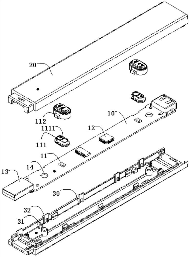
[0032] The following description serves to disclose the present invention to enable those skilled in the art to carry out the present invention. The preferred embodiments described below are only examples, and those skilled in the art can devise other obvious variations. The basic principles of the present invention defined in the following description can be applied to other embodiments, variations, improvements, equivalents and other technical solutions without departing from the spirit and scope of the present invention.

[0033] Those skilled in the art should understand that in the disclosure of the present invention, the terms "vertical", "transverse", "upper", "lower", "front", "rear", "left", "right", " The orientation or positional relationship indicated by "vertical", "horizontal", "top", "bottom", "inner", "outer", etc. is based on the orientation or positional relationship shown in the drawings, which are only for the convenience of describing the present invention...


PUM


Abstract

The invention discloses a laser induction strip and an induction method. The laser induction strip comprises a control chip, a PCB circuit board, a laser transceiver, a bottom plate and a cover plate,wherein the control chip is installed on the PCB circuit board, the laser transceiver is connected with the PCB and is electrically connected with the control chip, the PCB is mounted on the bottom plate, the cover plate covers an upper part of the PCB circuit board and is fixedly connected with the bottom plate, and two ends of the PCB are connected with a USB interface. According to the laser induction strip and the induction method provided by the invention, the induction distance is obtained by calculating the time difference between photon emission and reflection, so calculation accuracyof the distance of an induction object can be improved, and the induction distance of an object is increased.

Description

[0001] field of invention [0002] The invention relates to the field of laser induction, in particular to a laser induction strip and an induction method. [0003] Background of the invention [0004] Infrared sensing equipment for sensing objects usually includes an infrared emitting device and an infrared receiving device. The infrared emitting device emits infrared rays outward, and the infrared receiving device receives reflected infrared rays. In the prior art, the sensing of corresponding objects usually calculates the infrared rays reflected from the object end Intensity, and set the intensity threshold, if the received infrared reflection light intensity is less than the set threshold value, it can be judged that the item is outside the sensing range, if the received infrared reflection light intensity is greater than the set threshold value, it can be judged that the item is in the sensing range Within, the existing technical scheme only calculates the reflected light...

Claims


Application Information

Patent Timeline
IPC IPC(8): G01S17/08
CPCG01S17/08
Inventor 倪立成叶生暄宁显文孙小明沈雪丹周建波潘松卢肖杰
Owner 帷幄匠心科技(杭州)有限公司
Why Eureka
Try Eureka