Eureka AIR delivers breakthrough ideas for toughest innovation challenges, trusted by R&D personnel around the world.

Radial magnetic bearing structure and multi-degree-of-freedom magnetic levitation mechanism containing same

A magnetic bearing and axial technology, applied in the direction of magnetic bearings, bearings, shafts and bearings, etc., can solve the problems of being greatly affected by the magnetic gap and large power consumption, and achieve the effect of simple structure, low power consumption and good linearity

Active Publication Date: 2020-10-27
BEIJING INST OF CONTROL ENG
View PDF16 Cites 2 Cited by
  • Summary
  • Abstract
  • Description
  • Claims
  • Application Information

AI Technical Summary

Problems solved by technology

[0003] The technical problem to be solved by the present invention is to overcome the deficiencies of the prior art, provide a radial magnetic bearing structure and a multi-degree-of-freedom magnetic levitation mechanism including the structure, and solve the problem that the magnetic force of conventional magnetic bearings is greatly affected by the magnetic gap and the large load capacity The problem of high power consumption under force, to achieve the advantages of good linearity of output magnetic force, high stiffness, low power consumption, etc.

Method used


Image

  • Radial magnetic bearing structure and multi-degree-of-freedom magnetic levitation mechanism containing same
  • Radial magnetic bearing structure and multi-degree-of-freedom magnetic levitation mechanism containing same
  • Radial magnetic bearing structure and multi-degree-of-freedom magnetic levitation mechanism containing same

Examples


Embodiment 1

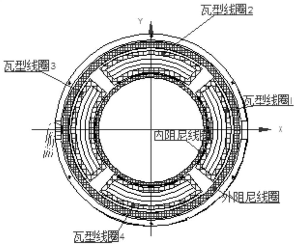
[0045] Such as figure 1 As shown, it is a sectional view of a typical structure of the radial magnetic bearing of this embodiment, that is, the basic form of the present invention, including an upper rotor assembly, a lower rotor assembly and a stator assembly.

[0046] The upper rotor assembly and the lower rotor assembly are used in pairs to form a main magnetic circuit to generate a constant axial vertical magnetic field; the stator assembly is located between the upper rotor assembly and the lower rotor assembly, and the stator coils are radially energized in pairs to generate electromagnetic force The radial translation is realized; the radial magnetic bearings are used in pairs in the axial direction to realize the control of the radial torsional degree of freedom. In this embodiment, the radial magnetic bearing is an inner rotor outer stator structure, such as figure 1 As shown, in this structure, the rotor is installed on the central axis of the inner ring bearing, th...

Embodiment 2

[0055] This embodiment also includes an upper rotor assembly, a lower rotor assembly, and a stator assembly.

[0056] The upper rotor assembly and the lower rotor assembly are used in pairs to form a main magnetic circuit to generate a constant axial vertical magnetic field; the stator assembly is located between the upper rotor assembly and the lower rotor assembly, and the stator coils radially The paired energization generates electromagnetic force to realize radial translation; the radial magnetic bearings are used in pairs in the axial direction to realize the control of the radial torsional degree of freedom.

[0057] The upper rotor assembly is composed of the upper rotor shell, the magnetic ring, the inner and outer magnetic steel rings and the magnetic gathering ring, and the inner and outer magnetic steel rings are placed between the magnetic conducting ring and the magnetic gathering ring by gluing; , magnetic conduction ring, inner and outer magnetic steel rings an...

Embodiment 3

[0065] Such as Figure 4 As shown, this embodiment has an outer rotor inner stator structure, and the design of the magnetic steel assembly and stator parameters is the same as that in Embodiment 1, except that the rotor should be installed on the outer circle, so the rotor shell is outside, and the stator should be installed on the inner shaft of the mechanism. That is, the stator seat is included.


PUM

PropertyMeasurementUnit
thicknessaaaaaaaaaa

Abstract

The invention relates to a radial magnetic bearing structure and a multi-degree-of-freedom magnetic levitation mechanism containing the structure. The structure comprises an upper rotator assembly, alower rotator assembly and a stator assembly. The structure is simple, processing is convenient, and the assembly precision is high. The upper rotator assembly and the lower rotator assembly form a high-strength permanent even perpendicular main magnetic field along the axial direction; the magnetic steel surfaces of the upper rotator assembly and the lower rotator assembly are wrapped with a layer of magnetic conductive materials, so an even flat magnetic field with a large occupation rate can be formed in a magnetic gap to achieve the magnetism gathering effect. The stator assembly is of a hollow disc structure and built-in coils in the stator assembly are radially utilized in pairs in the perpendicular even magnetic field to form a couple, so the output force of the coils during motionsin the magnetic gap is even, the linear degree is high, and the high rigidity and low disturbance index requirements of a radial magnetic bearing are realized. The structure solves the difficulty that existing the magnetic force of magnetic bearings is greatly influenced by changes of magnetic gaps and the power consumption is large under large load bearing force and realizes the advantages of good magnetic force linear degree, high rigidity and lower power consumption. The structure belongs to the field of astrovehicle magnetic control systems.

Description

technical field [0001] The invention relates to a radial magnetic bearing structure and a multi-degree-of-freedom magnetic levitation mechanism including the structure, in particular to a Lorentz force radial magnetic bearing, which belongs to non-contact magnetic levitation bearings applied to spacecraft, and can be used as a motor, Non-contact support of rotating parts in mechanical equipment such as swivel joints. The invention belongs to the technical field of spacecraft attitude control systems. Background technique [0002] With the low power consumption, ultra-stable and ultra-quiet requirements put forward by the actuator for magnetic levitation, and it is required that the stator and rotor can still achieve high-performance stable levitation when the relative displacement of the stator and rotor in the magnetic gap occurs, it is urgent to develop a magnetic force linearity within a certain motion gap. Good, low power radial magnetic bearings are used to achieve rad...

Claims


Application Information

Patent Timeline
Patent Type & Authority Applications(China)
IPC IPC(8): F16C32/04
CPCF16C32/044F16C32/0451F16C32/0478F16C32/0459F16C32/047
Inventor 杨磊樊亚红张激扬武登云张鹏波齐明王舒雁冯洪伟刘景辉李建普杜金龙吴芊杨泽琨
Owner BEIJING INST OF CONTROL ENG
Why Eureka
Eureka Blog
Learn More