Eddy-current damping wall and building

An eddy current damping and eddy current technology, applied in buildings, building components, building types, etc., can solve problems such as affecting the use function of the damping wall, high maintenance and repair costs, and inability to increase structural rigidity, and achieve low maintenance costs in the later period. Low maintenance cost and good durability

Pending Publication Date: 2020-10-27
HUNAN UNIV
View PDF12 Cites 3 Cited by
  • Summary
  • Abstract
  • Description
  • Claims
  • Application Information

AI Technical Summary

Problems solved by technology

[0009] The purpose of the present invention is: to solve the problem of viscous damping in the prior art, liquid leakage often occurs during long-term use, which seriously affects the use function of the damping wall, and the later maintenance and repair costs are high; it cannot be applied to the situation where the structural rigidity cannot be increased To solve the problem, provide an eddy current damping wall and building with little or no oil leakage, low maintenance cost and good durability, and the eddy current damping wall only produces damping, so that the eddy current damping wall of the present invention is also Can be applied to the situation where the structural rigidity cannot be increased

Method used


Image

  • Eddy-current damping wall and building
  • Eddy-current damping wall and building
  • Eddy-current damping wall and building

Examples


Embodiment 1

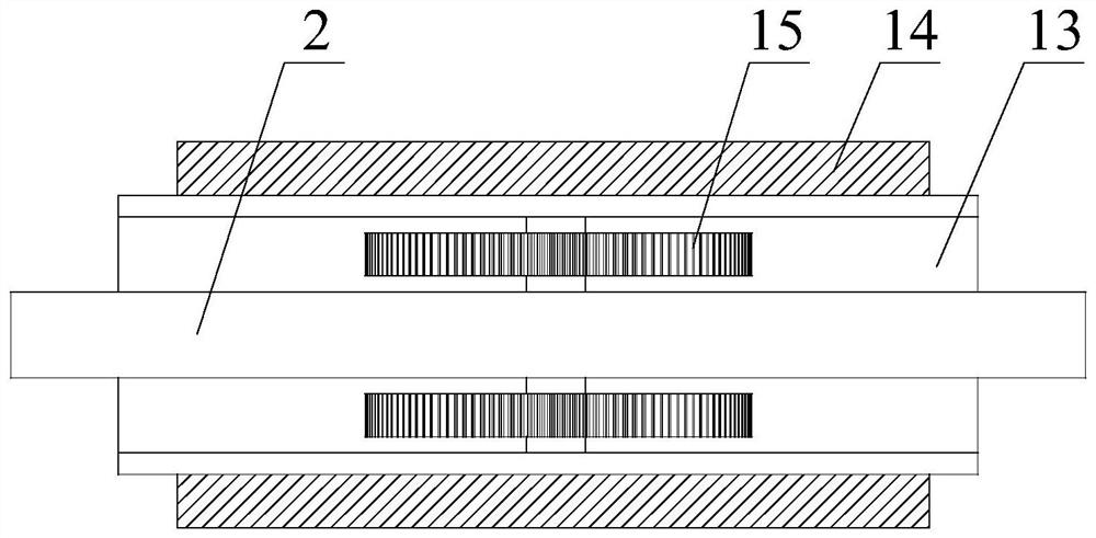
[0046] Such as Figure 1-3 As shown, a kind of eddy current damping wall described in this embodiment includes,

[0047] The first transmission shaft 8;

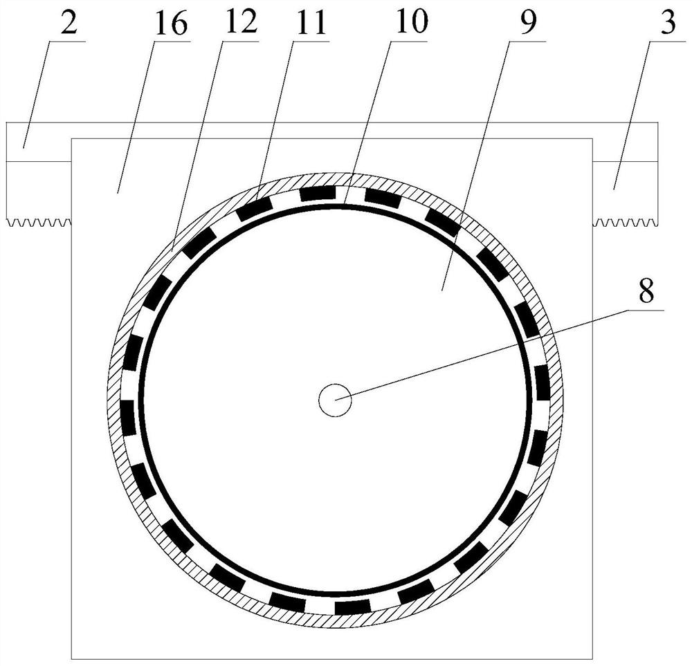
[0048] At least one eddy current assembly 14, the eddy current assembly 14 includes a conductor plate back iron 9 that is rotatably connected with the first transmission shaft 8, and the outside of the conductor plate back iron 9 is sequentially sleeved with a conductor plate 10 and a permanent magnet Back iron 12, the inner wall of the permanent magnet back iron 12 is provided with at least two permanent magnets 11, wherein at least two of the permanent magnets 11 are arranged at intervals along the inner wall of the permanent magnet back iron 12, and the permanent magnets 11 are generally set in pairs;

[0049]The transmission mechanism 15 is drivingly connected with the first transmission shaft 8, and the transmission mechanism 15 is used to convert the linear motion into the rotation of the first transmission shaft 8. ...

Embodiment 2

[0057] Such as Figure 4 As shown, a building with an eddy current damping wall described in this embodiment includes a kind of eddy current damping wall as described in Embodiment 1 and a substructure 17 connected to the side plate 16, and The rack 3 is connected to the superstructure 1, and the substructure 17 is generally a floor or a beam below the side plate 16; the superstructure 1 is generally a floor or a beam above the rack 3;

[0058] When in use, the lower building structure 17 is connected to the side plate 16 for supporting the rigid frame 13, and the upper building structure 1 is connected to the rack 3, so that the rack 3 can connect the upper building structure 1 The linear motion also includes some slight swings converted into the rotation of the first transmission shaft 8, the first transmission shaft 8 drives the conductor plate back iron 9 and the conductor plate 10 to cut the magnetic field lines generated by the permanent magnet 11, and then the conductor...


PUM


Abstract

The invention relates to the field of buildings, in particular to an eddy-current damping wall and a building. The eddy-current damping wall comprise a first transmission shaft, at least one eddy current assembly and a transmission mechanism. The eddy current assembly comprises conductor plate back iron rotationally connected with the first transmission shaft, the outer side of the conductor plateback iron is sleeved with a conductor plate and permanent magnet back iron in sequence, at least two permanent magnets are arranged on the inner wall of the permanent magnet back iron, and the at least two permanent magnets are arranged in the circumferential direction of the permanent magnet back iron at intervals. The transmission mechanism is in driving connection with the first transmission shaft, and is used for converting linear motion into rotation of the first transmission shaft. According to the eddy-current damping wall, the eddy current assembly and the transmission mechanism are adopted as a main structure, an oil leakage phenomenon rarely happens or is avoided, the later maintenance charge is low, and the durability is good; and the eddy-current damping wall only generates damping, and therefore the eddy-current damping wall can also be suitable for the situation that the structural rigidity cannot be improved.

Description

technical field [0001] The invention relates to the building field, in particular to an eddy current damping wall and a building. Background technique [0002] Under the action of wind and earthquake loads, the building vibrates greatly, which seriously affects the safety and durability of the building. Measures should be taken to reduce the vibration (vibration) of the building. The damping wall is a passive energy-dissipating component, which uses the relative movement between the structural layers and is installed as a wall between the building layers to increase the damping of the structure to achieve energy dissipation and shock absorption. Compared with other energy dissipation and shock absorbing devices, the damping wall has the following advantages: [0003] (1) Easy to manufacture and install without complicated devices; [0004] (2) The wall area is larger and consumes more vibration energy; [0005] (3) Install the damping wall on the wall of the building with...

Claims


Application Information

Patent Timeline
Patent Type & Authority Applications(China)
IPC IPC(8): E04B2/00E04B1/98E04H9/02
CPCE04B2/00E04B1/98E04H9/021
Inventor 李寿英李亚峰毛伟阳牛华伟陈政清
Owner HUNAN UNIV
Why Eureka
Try Eureka