A steel silo unloading device

A technology of unloading device and steel silo, applied in the field of steel silo, can solve the problems of excessively fast cutting, dead zone of side wall, affecting the storage capacity of steel plate, etc., and achieve the effect of preventing hardening, improving fluidization capacity, and alleviating material hardening.

Active Publication Date: 2022-07-22
鱼台县旺星粮油机械制造有限公司
View PDF20 Cites 0 Cited by
  • Summary
  • Abstract
  • Description
  • Claims
  • Application Information

AI Technical Summary

Problems solved by technology

[0004] This blanking method has a small diameter in the powder steel silo, and both the silo wall and the central blanking can unload the material under the action of gravity. When the diameter of the powder steel silo becomes larger, the distance between the wall and the center is at the center. The distance of the decompression cone is increased, and the activated material can directly enter the decompression cone under the action of gravity near the feed port on the edge of the decompression cone. The material near the side wall will enter the decompression cone or the mixing chamber depending on the sliding force generated on the slope. The sliding force is the component force of gravity, which is much smaller than the vertical gravity. As the diameter increases, the resistance of the material near the center becomes greater and greater, making it extremely difficult for the material on the edge of the warehouse wall to move to the decompression cone or the mixing chamber in the center, while the material near the center is discharged too quickly, so that The upper powder material in the central part can be discharged quickly, while the material on the side wall does not move for a long time. When the material is discharged, the compressed air blown into the inflatable box in the warehouse contains moisture, which is combined with the material on the edge of the warehouse wall for a long time. Dynamically form a dead material area that cannot be moved, so that materials with hydration properties such as powder and mineral powder will produce plate-forming material, which not only affects the storage capacity of the steel silo, but also affects the homogenization of the steel silo, resulting in large-scale Side wall dead zone phenomenon in steel silo

Method used


Image

  • A steel silo unloading device
  • A steel silo unloading device
  • A steel silo unloading device

Examples


Embodiment

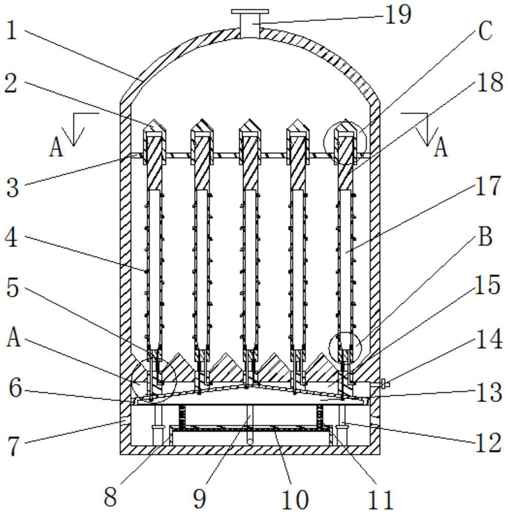
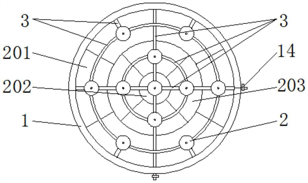
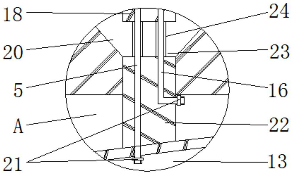
[0033] like figure 1 The shown unloading device for a steel silo includes a silo shell 1, and the upper and lower ends of the silo shell 1 are respectively provided with a feeding port 19 and a discharging port 7; There is a partition whose periphery is completely fitted with the inner wall of the silo shell 1, and the inner side of the silo shell 1 is divided into an upper chamber for storing materials and a lower chamber for installing driving components. The upper part of the partition is provided with A plurality of conical funnel-shaped unloading areas 20, and the lower part of the partition is provided with a one-to-one correspondence with the unloading area 20 and is connected with the bottom of the unloading area 20 and the lower chamber. Each of them is telescopically provided with a blocking rod 22 whose periphery is completely attached to the side wall of the discharge port. The lower end of each blocking rod 22 is jointly connected with a first piston plate 6 locat...


PUM


Abstract

The invention discloses a steel silo unloading device, belonging to the field of steel silo. The bottom of each feeding area is provided with a feeding port, each feeding port is provided with a blocking rod, and the lower end of the blocking rod is jointly connected with a first block located in the lower chamber. The piston plate, the lower part of the peripheral side of the silo shell is provided with a discharge port that can be connected with the lower side of the first piston plate; the upper end of the blocking rod is connected with a lifting rod, and the upper end face of the lifting rod is higher than the upper end face of the material; The inner side of the rod is provided with an air supply cavity, and the lifting rod is spirally distributed with air nozzles connected to the air supply cavity at equal intervals along the height direction. . The discharging uniformity of the invention is good, and the material can be effectively prevented from being hardened.

Description

technical field [0001] The invention relates to the field of steel silos, in particular to a steel silos unloading device. Background technique [0002] At present, various steel silos are mainly used to store powder, granular and other materials, and are widely used in all walks of life. The scale of the steel silo increases with the expansion of the production line. In the past high-speed development of industrialization, most of the methods for increasing the storage capacity of the powder steel silo are to increase the diameter of the silo and maintain its original height-diameter ratio. For the large-scale powder steel silo, while the capacity of the powder silo is increased, the internal structure of the silo has not been upgraded and improved, and the original blanking structure and the original blanking method are still maintained. [0003] The method of unloading is to inject compressed air into the inflatable box, and the compressed air reaches the material layer ...

Claims


Application Information

Patent Timeline
Patent Type & Authority Patents(China)
IPC IPC(8): B65D88/70B65D88/72B65D88/54B65D88/64
CPCB65D88/703B65D88/72B65D88/54B65D88/64
Inventor 包春梅
Owner 鱼台县旺星粮油机械制造有限公司
Why Eureka
Try Eureka